Getting Started with the ASL5115EVBSLAV
Contents of this document
-
Get Started
-
Know the Board
-
Configure Hardware
-
Install Software
Sign in to save your progress. Don't have an account? Create one.
Purchase your ASL5115EVBSLAV
1. Get Started
The NXP analog product development boards provide an easy-to-use platform for evaluating NXP products. The boards support a range of analog, mixed-signal, and power solutions. They incorporate monolithic integrated circuits and system-in-package devices that use proven high-volume technology. NXP products offer longer battery life, a smaller form factor, reduced component counts, lower cost, and improved performance in powering state-of-the-art systems.
This page will guide you through learning about how to set up the ASL5115EVBMST evaluation board leader and follower ASL5115EVBSLAV.
1.1 Kit Contents and Packing List
The ASL5115EVBSLAV contents include:
- Assembled and tested evaluation board
1.2 Required Equipment
Working with the ASL5115EVBMST and the ASL5115EVBSLAV requires the kit contents, additional hardware and a Windows PC workstation with installed software.
- 12 V power supply. Current requirements depend on intended loads (number of follower board hanging from Leader board). The current consumption of each module has to be considered as 0.015 A
- S32K144EVB-Q100 to control the Matrix LED Controller's evaluation board (only in case of GUI usage)
- The NXP LED Drivers and Controllers application; a Graphical User Interface (GUI). Available in DocStore
- (Optional) Vector CANoe software (Vector ). Already developed simulations available in DocStore
- This kit may be used with the user's own software or different stimuli sources; however, those tools are not part of this documentation
1.3 System Requirements
This evaluation board requires a Windows PC workstation. Meeting these minimum specifications should produce great results when working with this evaluation board.
- USB-enabled computer with Windows 7, Windows 8, or Windows 10
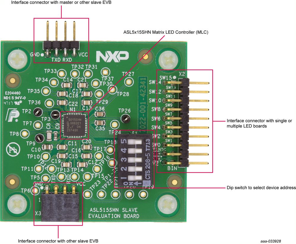
2. Know the Board
2.1 Board Overview
ASL5115EVBSLAV features the ASL5115SHN. The ASL5xxxyHz family is a fully featured and flexible Matrix LED Controller (MLC). It provides a cost-effective design solution, specifically targeting advanced automotive exterior lighting applications. ASL5115SHN is controlled in direct mode, where the microcontroller updates the PWM information of each channel in a determined cycle. ASL5115SHN offers a 12-bit resolution in the PWM output, ensuring a smooth dimming performance to avoid glitches in the output light.
2.2 Boards Features
The ASL5115EVBSLAV board features include:
- Interface connector to attach the ASL5115EVBMST Matrix LED Controller (MLC)
- ASL5115EVBSLAV can be daisy chained with up to 9 follower boards that hang from a single Leader board
- Dip switch to select device addresses
- Populated with ASL5115SHN Matrix LED controller
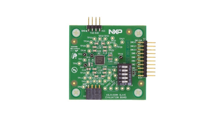
2.3 Board Image
Modular Follower EVB for Matrix LED Controller (MLC) ASL5115SHN connects to
2.4 ASL5115EVBMST Evaluation Board
The leader board is populated with one UJA1163 System Basic Chip (SBC) IC, to enable the communication with the microcontroller or Vector CANoe through CAN (FD) protocol, and to supply the MLC populated in the same board, together with the MLCs populated in the follower boards hanging from the leader board. A maximum of 9 follower boards can hang from a single leader board.
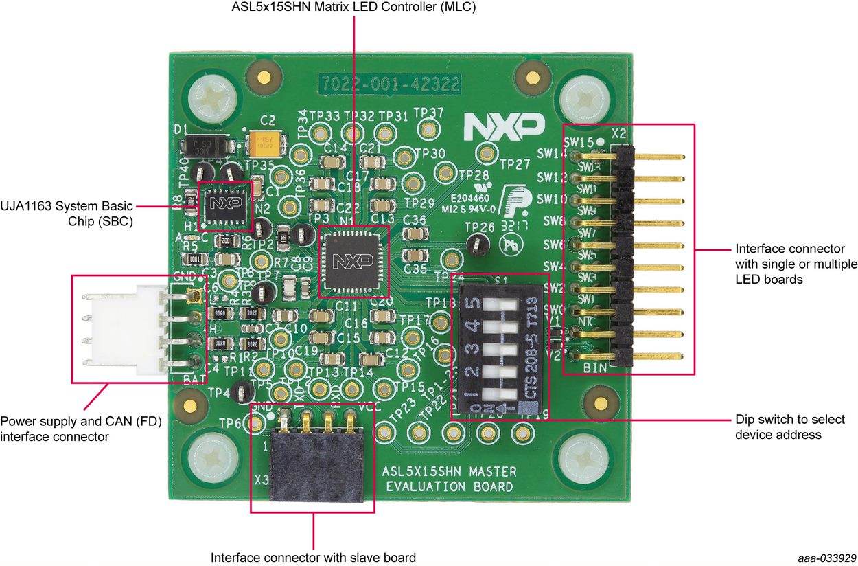
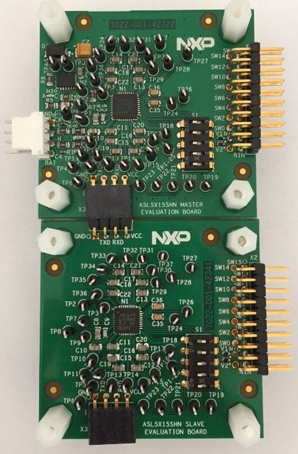
2.5 ASL5115EVBSLAV Evaluation Board Daisy Chain
Example of connection between a leader board and a follower board. Up to 9 follower boards can hang from a single Leader board. If there is one or several follower EVBs in the system, create a chain with the leader board using connectors X1 and X3. Also attach customer LED boards to the follower EVBs.
2.6 Accessory Boards
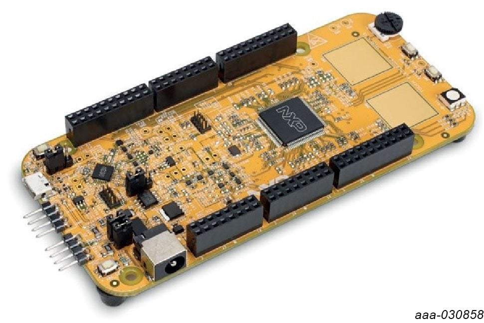
The ASL5115EVBMST is compatible with the S32K144EVBQ100. The S32K144EVB-Q100 provides the control signals (through CAN (FD) communication) for the ASL5x15SHN devices. When used with the GUI, the S32K144EVBQ100 drives the channels in the way as selected on the GUI. The S32K144EVB-Q100 can also be used as a system processor to create standalone applications or prototype systems.
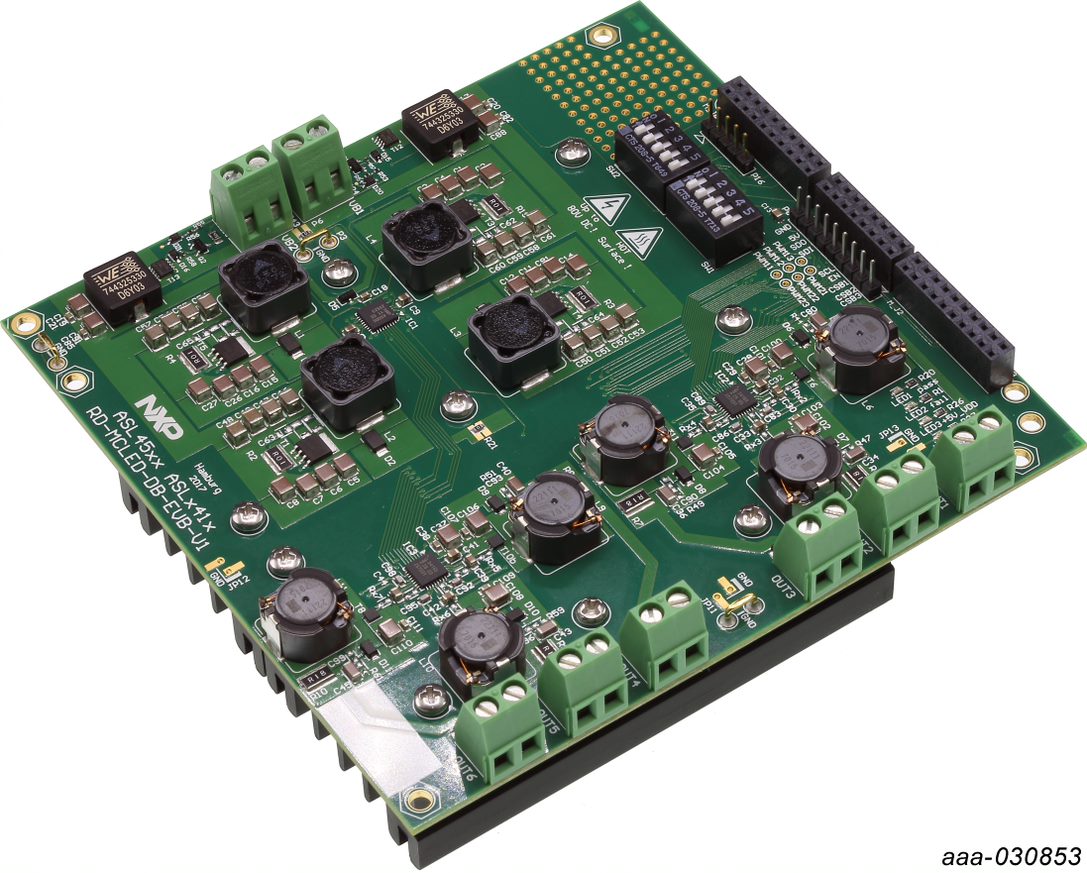
2.7 ASL45XASLX41 - Multichannel LED Driver System Evaluation Board
The ASLx500SHN and ASLx41xSHN Evaluation Board (EVB) features the ASL4500SHN, a highly integrated and flexible four-phase DC-to-DC boost converter IC and two ASL3416SHN, a three-channel buck mode LED driver IC delivering constant average DC current. The kit is designed to drive six LED strings with 150 mA to 1.6 A and 2 V to 60 V LED string voltage. In a default application a microprocessor unit (MCU) controls the devices through a serial peripheral interface (SPI).
The ASL5x15EVBMST is only connected to the CAN physical bus of the S32K144EVBQ100 and to the LEDs. The ASL5x15EVBMST EVB is not directly connected to the ASL45XASLX41. More information on the connection of the ASL45XASLX41 EVB can be found in the ASL45XASLX41 User guide (NDA required).
3. Configure Hardware
3.1 Hardware Configuration
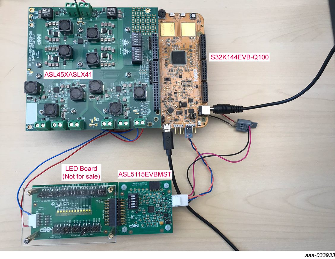
A full system configuration is completed with the ASL5115EVBMST wired with cable harness for power supply and CAN (FD) communication to the S32K144EVBQ100 associated by the connectors on the ASL45XASLX41 Multichannel LED board. Can also be configured with up to 9 ASL5115EVBSLAV follower boards not shown. Customer can configure using their own LED board.
3.2 Configuration Image
To start working with the ASL5x15EVB, the following connections and setup must be performed:
- Connect the ASL5115EVBMST to the S32K144EVB. Do not forget to supply S32K144EVB-Q100 with 12 V, to enable the CAN communication through the SBC
- With power turned off, attach S32K144EVB-Q100 12 V DC power supply to ASL5115EVBMST's supply terminals
- Attach an LED board (example shown in image) to the ASL5115EVBMST. Additionally, if there is one or several follower EVB in the system, create a chain with the leader board using connectors
X1andX3 - (Optional) If using the optional ASL45XASLX41: attach the S32K144EVBQ100 to ASL45XASLX41, and supply the LED boards with any of the available buck outputs
- Plug the USB cable from the mini connector end into the S32K144EVB-Q100
- Plug the USB cable standard connector end into the computer
- Turn on the power supply. The supply indicator LED (Red
LEDin ASL5x15EVBMST) (GreenLED3andLED4in ASL45XASLX41) shall light up - (Optional) Use GUI to drive all the evaluation boards (S32K144EVB-Q100, ASL45XASLX41 and all MLC's evaluation boards)
- (Optional) Use Vector CANoe software to drive MLC's evaluation boards
- (Optional) Use your own software, microcontroller and LED driver module to evaluate the NXP's Matrix LED Controller using its EVB
4. Install Software
4.1 Preparing Graphical User Interface Operating Environment
There are several steps to follow for the full system configuration using the ASL5115EVBMST, ASL5115EVBSLAV, S32K144EVB-Q100, and the ASL45XASLX41 evaluation boards.
4.2 Downloading and Flashing the S32K144EVB-Q100
To download and install the latest version of the S32K144EVB-Q100 software:
- Go to ASL45XASLX41
- Go to the Get Started section and download the Software and Design files (NDA required)
- Unzip the files to your computer
Flash the S32K144EVB-Q100:
- Connect the S32K144EVB-Q100 to your PC with a micro USB cable
- The S32K144EVB-Q100 is shown as a USB drive
- Copy the flash image (
*.srec) file from the one downloaded and unzipped before to the root directory of the S32K144EVB-Q100 USB drive - The copy process will take about one minute. Once completed, the S32K144EVBQ100 is flashed and is ready to be used with the GUI, the ASL5x15EVBMST, ASL5x15EVBSLAV and the ASL45XASLX41
4.3 Launching the GUI on Your Computer
The GUI provides easy control of all ASL5x15 EVB and ASL45XASLX41 EVB. To launch the GUI:
- Locate the GUI folder where you unzipped the GUI
- Start the GUI by calling the executable (
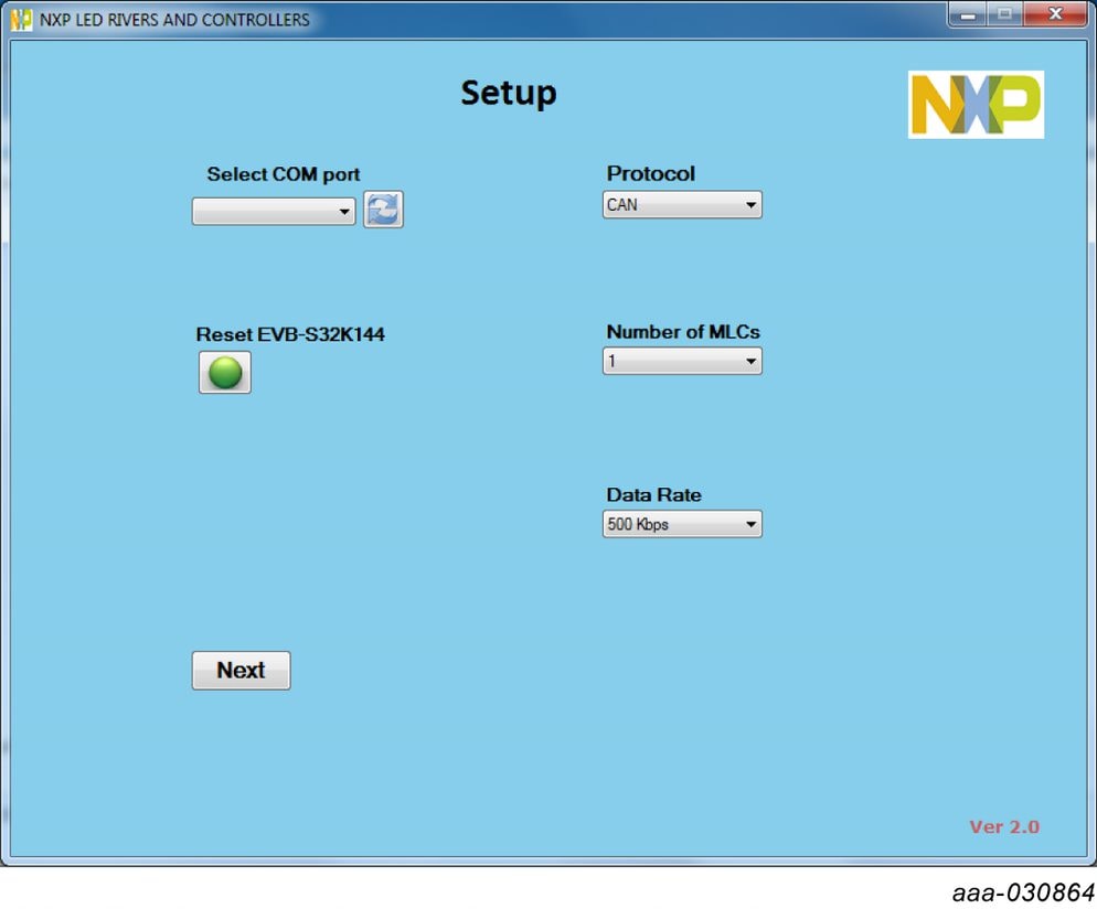
*.exe) file - The GUI opens with the startup window
The GUI is divided into several pages. Each page gives some control options to the user. The GUI will always start up with the Setup page.
Design Resources
Board Information
Software and hardware instructions are detailed in the UM11224: ASL5x15 Evaluation Boards - User Guide .
Additionally, enabling instructions are available on the S32K144EVB tool summary page.
Chip Documents
Additional References
Product Summary Page
ASL5xxxyHz: Smart Matrix LED Controller for Automotive Lighting.
Tool summary page
The overview section provides a description of the device, product features, a list of the kit contents, a list of (and links to) supported devices, list of (and links to) any related products and a Get Started section.
- Specifications: board technical specifications and features
- Documentation and Software: download current supporting documentation and software files
- Buy/Parametrics: purchase the product and view the product parametrics and kit contents
- Get help: supporting information such as communities and partner information
After downloading files, review each file, including the user guide which includes setup instructions.
For the Entire Solution
In addition to our ASL5xxxyHZ family Smart Matrix LED Controller for Automotive Lighting devices you may also want to visit:
Product pages:
- S32K: 32-bit Automotive General-Purpose Microcontrollers page
- ASL341ySHN: Three-channel Automotive LED Buck Driver
- ASL241ySHN: Two-channel Automotive LED Buck Driver
- ASL250ySHN: Two-Phase Automotive LED Boost Driver with a Limp Home mode
- ASL4500SHN: Four-Phase Automotive LED Boost Driver
- ASL150ySHN: Single-Phase Automotive LED Boost Driver with Limp Home mode
Tool pages:
- S32K144EVB: S32K144 Evaluation Board
- ASL45XASLX41: Multi-channel LED driver system
Support pages:
Hardware pages:
Software pages:
On this page
- 2.1
Board Overview
- 2.2
Boards Features
- 2.3
Board Image
- 2.4
ASL5115EVBMST Evaluation Board
- 2.5
ASL5115EVBSLAV Evaluation Board Daisy Chain
- 2.6
Accessory Boards
- 2.7
ASL45XASLX41 - Multichannel LED Driver System Evaluation Board