Getting Started with the MIMXRT1020-EVK
Contents of this document
-
Plug It In
-
Get Software
-
Build, Run
Sign in to save your progress. Don't have an account? Create one.
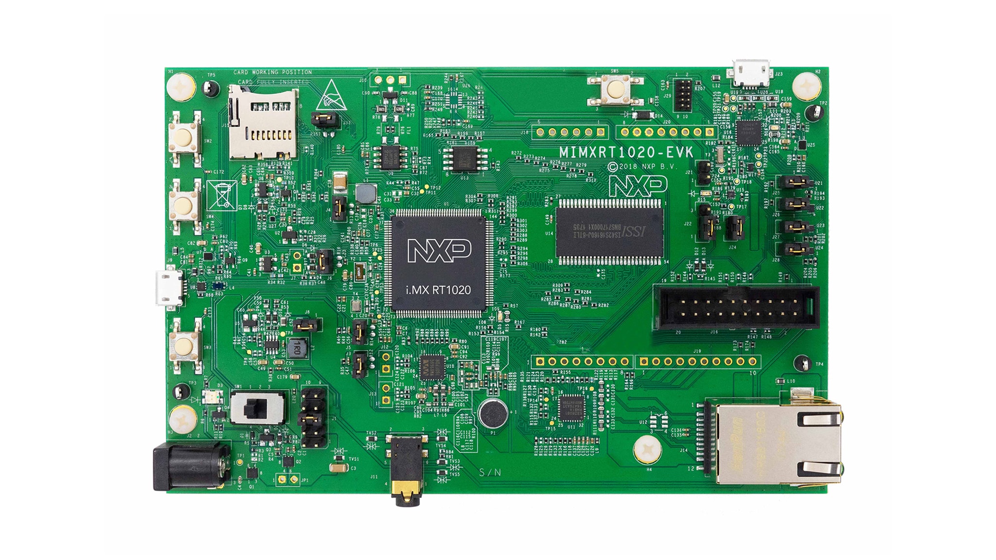
Purchase your i.MX RT1020 Evaluation Kit
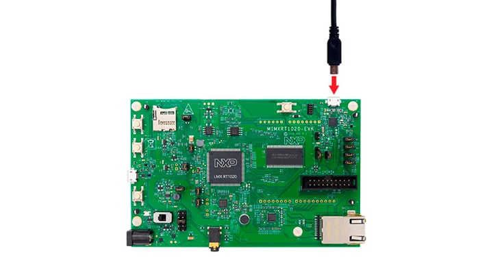
1. Plug It In
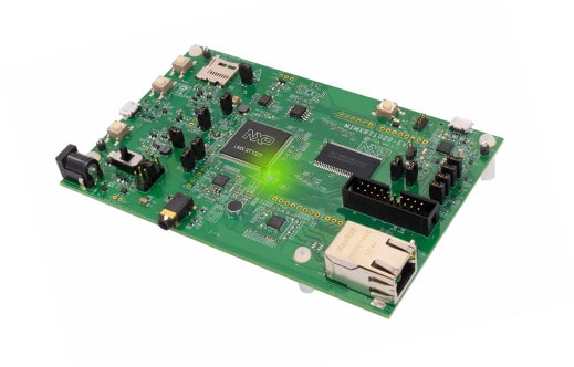
Let's take your MIMXRT1020-EVK for a test drive! You have the choice of watching the sequence in a short video or following the detailed actions list below.
1.1 Get Started With MIMXRT1020-EVK Development Platform - How to
2. Get Software
2.1 Choose a Development Path
MCUXpresso Software Development Kit (SDK) + Integrated Development Environment (IDE)
- True debug support via SWD and JTAG
- High software flexibility
- Full set of peripheral drivers with source
- Application examples and project files
Zephyr™ OS
- A scalable, open source real-time operating system (RTOS)
- Supports multiple hardware architectures
- Optimized for resource constrained devices
- Built with security in mind
To find our more, visit the Zephyr OS developer website.
2.2 Installing software for the MIMXRT1020-EVK
2.3 Jump Start Your Design with the MCUXpresso SDK
The MCUXpresso SDK is complimentary and includes full source code under a permissive open-source license for all hardware abstraction and peripheral driver software. Learn more about SDK.
Click below to download a pre-configured SDK release for the MIMXRT1020-EVK

You can also use the online SDK Builder to create a custom SDK package for the MIMXRT1020-EVK using the SDK builder.
2.4 Install Your Toolchain
NXP offers a complimentary toolchain called MCUXpresso IDE.
 Get MCUXpresso IDE
Want to use a different toolchain? No problem! The MCUXpresso SDK includes support for other tools such as IAR, Keil, and command-line GCC.

2.5 PC Configuration
Many of the example applications output data over the MCU UART so you'll want to make sure that the driver for the board's virtual COM port is installed. Before you run the driver installer, you MUST have the board plugged into your PC.
Download Driver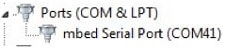
With the serial port driver installed, run your favorite terminal application to view the serial output from the MCU's UART. Configure the terminal to 115200 baud rate, 8 data bits, no parity and 1 stop bit. To determine the port number of the MIMXRT1020-EVK virtual COM port, open the device manager and look under the "Ports" group.
Not sure how to use a terminal application? Try one of these tutorials: Tera Term Tutorial, PuTTY Tutorial.
3. Build, Run
3.1 Build and Run SDK Demos on the MIMXRT1020-EVK
3.2 Explore the MCUXpresso SDK Example Code
The MCUXpresso SDK comes with a long list of example application code. To see what's available, browse to the SDK boards folder of your SDK installation and select your board, the MIMXRT1020-EVK:
<sdk_install_directory>/boards/evkmimxrt1020</sdk_install_directory>.To learn more about specific example code, open the readme.txt file in an example’s directory.
3.3 Build, Run and Debug MCUXpresso SDK Examples
If one or more of the demo applications or driver examples sounds interesting, you're probably wanting to know how you can build and debug yourself. The Getting Started with MCUXpresso SDK guide provides easy, step-by-step instructions on how to configure, build and debug demos for all toolchains supported by the SDK.
Use the guide below to learn how to open, build and debug an example application using MCUXpresso IDE.
Use MCUXpresso IDE
Import the MCUXpresso SDK
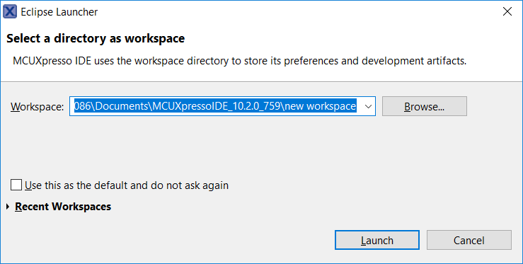
- Open MCUXpresso IDE
- Choose a directory on your computer as a workspace.
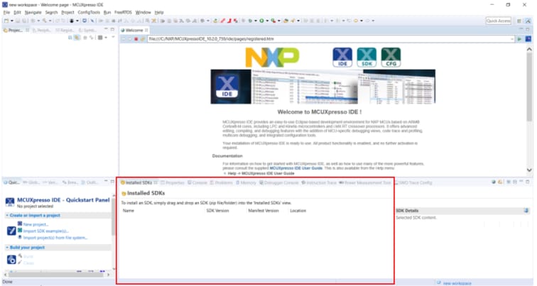
- Switch to the Installed SDKs view within the MCUXpresso IDE window.
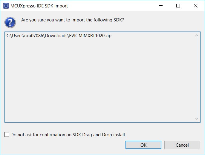
- Open Windows Explorer, and drag and drop the EVK-MIMXRT1020 SDK zip file into the Installed SDKs view.
- You will get a prompt as follows. Click on OK to continue the import:
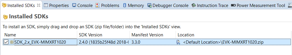
- The installed SDK will appear in the Installed SDKs view as shown below:
Build an Example Application
-
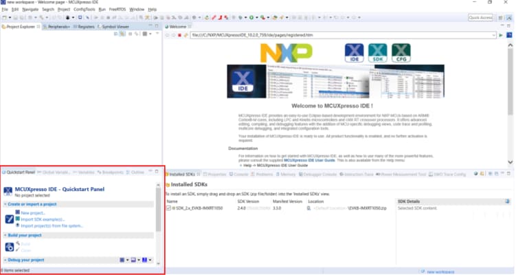
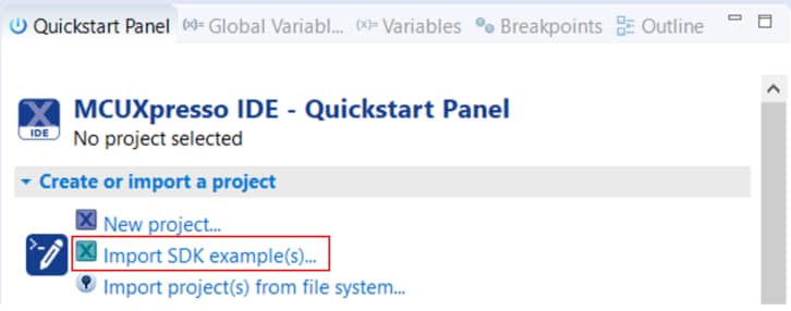
Find the Quickstart Panel in the lower left hand corner
-
Then click on Import SDK examples(s)…
-
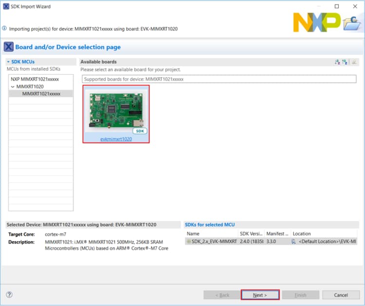
Click on the evkmimxrt1020 board to select that you want to import an example that can run on that board, and then click on Next.
-
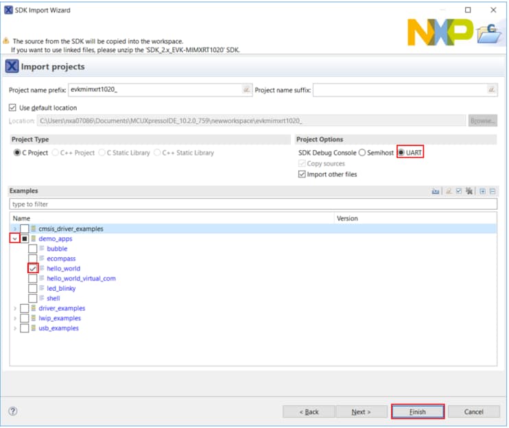
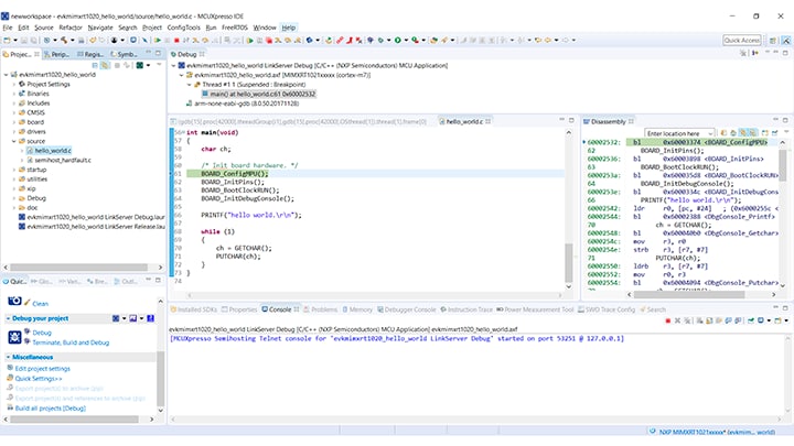
Use the arrow button to expand the demo_apps category, and then click the checkbox next to hello_world to select that project. Make sure UART is selected as the SDK Debug Console. Then, click on Finish.
-
Now build the project by clicking on the project name and then click on the Build icon.
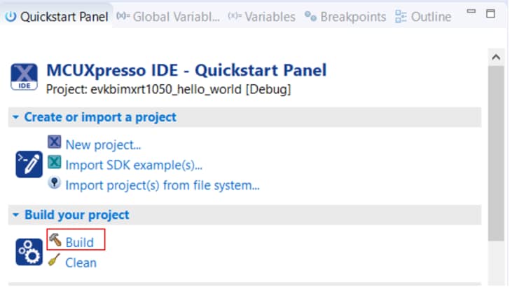
-
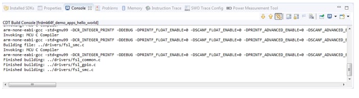
You can see the status of the build in the Console tab.
Run an Example Application
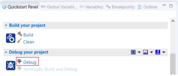
- Now that the project has been compiled, you can now flash it to the board and run it.
- Make sure the USB cable is plugged into the OpenSDA debug connector on the MIMXRT1020-EVK, and click on Debug in the QuickStart Panel.
-
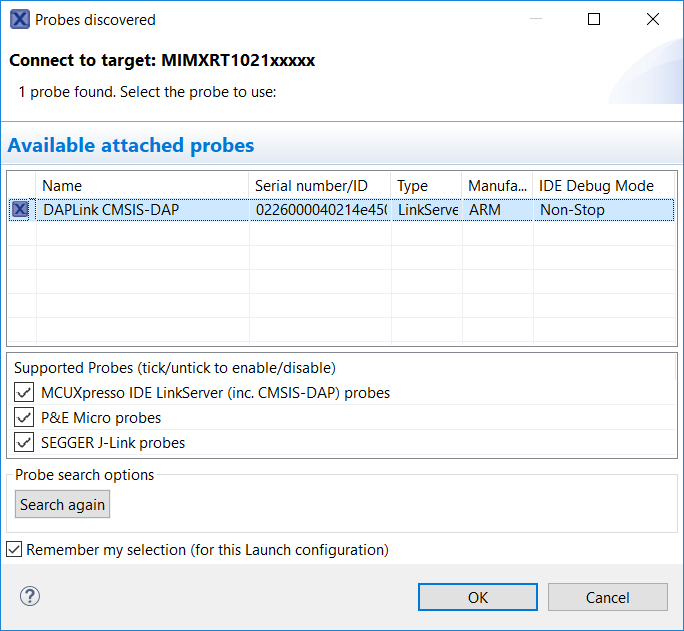
MCUXpresso IDE will probe for connected boards and should find the CMSIS-DAP debug probe that is part of the integrated OpenSDA circuit on the MIMXRT1020-EVK. Click on OK to continue.
-
The firmware will be downloaded to the board and the debugger started.
-
Open up a terminal program and connect to the COM port the board enumerated as. Use 115200 baud 8 data bits, no parity and 1 stop bit.
-
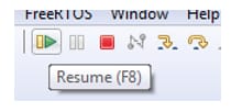
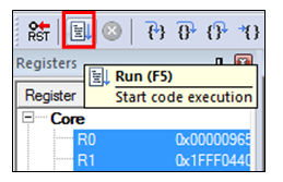
Start the application by clicking the "Resume" button:
-
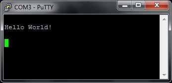
The hello_world application is now running and a banner is displayed on the terminal. If this is not the case, check your terminal settings and connections.
-
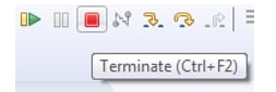
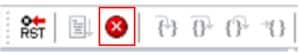
Use the controls in the menu bar to pause, step into, and step over instructions and then stop the debugging session by click on the Terminate icon:
Using a different toolchain?
Use IAR EWArm
Build an Example Application
The following steps guide you through opening the hello_world example application. These steps may change slightly for other example applications as some of these applications may have additional layers of folders in their path.
-
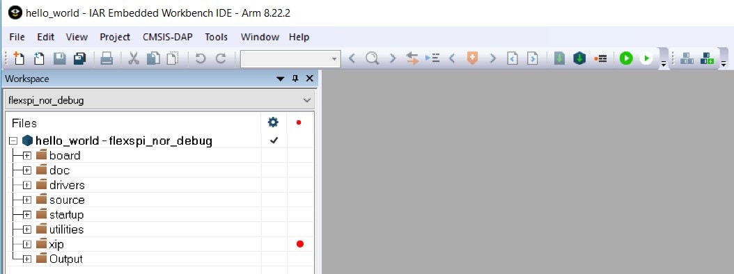
If not already done, open the desired demo application workspace. Most example application workspace files can be located using the following path:
<install_dir>/boards/<board_name>/<example_type>/<application_name>/iar</application_name>
</example_type></board_name ></install_dir >
Using the the hello_world demo as an example, the path is located in:
<install_dir>/boards/evkmimxrt1020/demo_apps/hello_world/iar/hello_world.eww</install_dir> -
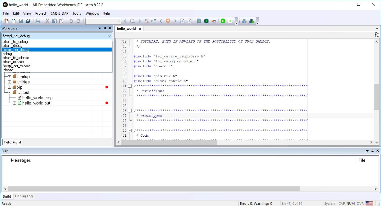
Select the desired build target from the drop-down.
For this example, select the “hello_world – flexspi_nor_debug” target.
-
To build the demo application, click the “Make” button, highlighted in red below.
Run an Example Application
To download and run the application, perform these steps:
- Connect the development platform to your PC via USB cable.
-
Open the terminal application on the PC, such as PuTTY or TeraTerm, and connect to the debug COM port. Configure the terminal with these settings:
- 115200 baud rate, (reference BOARD_DEBUG_UART_BAUDRATE variable in board.h file)
- No parity
- 8 data bits
- 1 stop bit
-
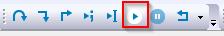
In IAR, click the "Download and Debug" button to download the application to the target.

-
The application is then downloaded to the target and automatically runs to the main() function.
-
Run the code by clicking the "Go" button to start the application.
-
The hello_world application is now running and a banner is displayed on the terminal. If this is not true, check your terminal settings and connections.
Use Keil® MDK
Install CMSIS Device Pack
After the MDK tools are installed, Cortex® Microcontroller Software Interface Standard (CMSIS) device packs must be installed to fully support the device from a debug perspective. These packs include things such as memory map information, register definitions and flash programming algorithms. Follow these steps to install the MIMXRT102x CMSIS pack.
-
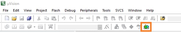
Open the MDK IDE, which is called µVision. In the IDE, select the "Pack Installer" icon.
-
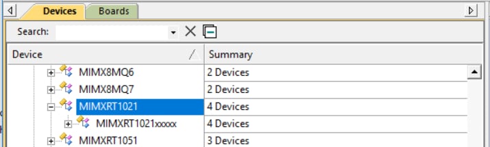
In the Pack Installer window, navigate to the Devices tab and select the MIMXRT1021 device under NXP.
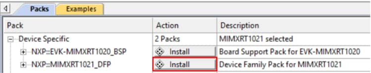
- In the Packs tab, install the DFP for the MIMXRT1020-EVK board. The DFP is named NXP::MIMXRT1021_DFP. Click on the "Install" button next to the pack. This process requires an Internet connection to successfully complete.
-
After the installation finishes, close the Pack Installer window and return to the µVision IDE.
Build the Example Application
The following steps will guide you through opening the hello_world application. These steps may change slightly for other example applications as some of these applications may have additional layers of folders in their path.
-
If not already done, open the desired demo application workspace in:
<install_dir >/boards/<board_name >/<example_type>/<application_name>/mdk</application_name>
</example_type></board_name ></install_dir >
The workspace file is named
<demo_nam>.uvmpw, so for this specific example, the actual path is: </demo_nam><install_dir>/boards/evkmimxrt1020/demo_apps/hello_world/mdk/hello_world.uvmpw</install_dir> -
To build the demo project, select the "Rebuild" button, highlighted in red.

-
The build completes without errors.
Run an Example Application
To download and run the application, perform these steps:
-
Connect the development platform to your PC via USB cable.
-
Open the terminal application on the PC, such as PuTTY or TeraTerm, and connect to the debug serial port number. Configure the terminal with these settings:
- 115200 baud rate, (reference BOARD_DEBUG_UART_BAUDRATE variable in board.h file)
- No parity
- 8 data bits
- 1 stop bit
-
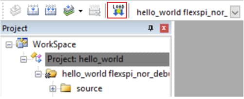
After the application is properly built, click the "Load" button to download the application to the target.
-
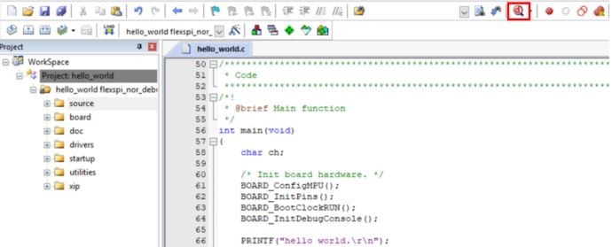
To debug the application, click the “Start/Stop Debug Session” button, highlighted in red.
-
Run the code by clicking the "Run" button to start the application.
-
The hello_world application is now running and a banner is displayed on the terminal. If this is not true, check your terminal settings and connections.

- Press Stop to end the debug session.
Use Arm® GCC
Set Up Toolchain
This section contains the steps to install the necessary components required to build and run a KSDK demo application with the Arm GCC toolchain, as supported by the Kinetis SDK. There are many ways to use Arm GCC tools, but this example focuses on a Windows environment. Though not discussed here, GCC tools can also be used with both Linux OS and Mac OSX.
Install GCC Arm Embedded Toolchain
Download and run the installer from GNU Arm Embedded Toolchain. This is the actual toolchain (i.e., compiler, linker, etc.). The GCC toolchain should correspond to the latest supported version, as described in the Kinetis SDK Release Notes.
Install MinGW
The Minimalist GNU for Windows (MinGW) development tools provide a set of tools that are not dependent on third party C-Runtime DLLs (such as Cygwin). The build environment used by the KSDK does not utilize the MinGW build tools, but does leverage the base install of both MinGW and MSYS. MSYS provides a basic shell with a Unix-like interface and tools.
-
Download the latest MinGW mingw-get-setup installer from MinGW - Minimalist GNU for Windows Files.
-
Run the installer. The recommended installation path is C:\MinGW, however, you may install to any location.
-
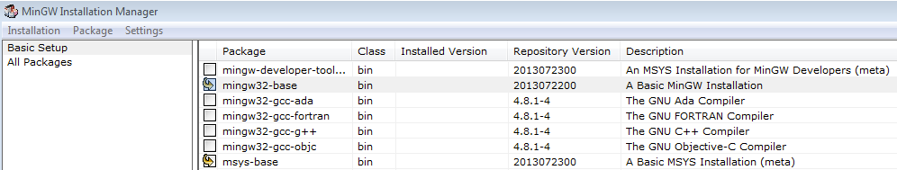
Ensure that the "mingw32-base" and "msys-base" are selected under Basic Setup.
-
Click "Apply Changes" in the "Installation" menu and follow the remaining instructions to complete the installation.
-
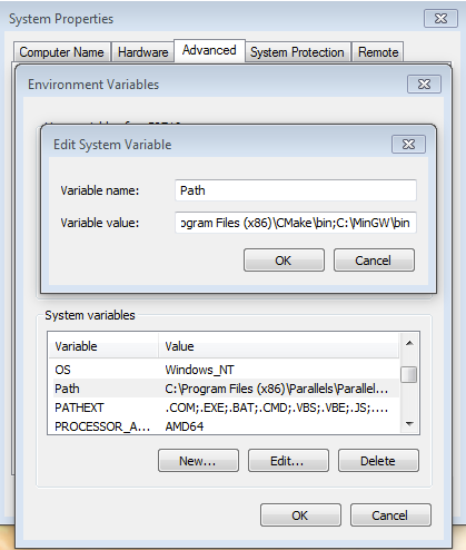
Add the appropriate item to the Windows operating system Path environment variable. It can be found under Control Panel -> System and Security -> System -> Advanced System Settings in the "Environment Variables..." section. The path is:
<mingw_install_dir>\bin</mingw_install_dir>Assuming the default installation path, C:\MinGW, an example is shown below. If the path is not set correctly, the toolchain does not work.
If you have "C:\MinGW\msys\x.x\bin" in your PATH variable (as required by KSDK 1.0.0), remove it to ensure that the new GCC build system works correctly.
-
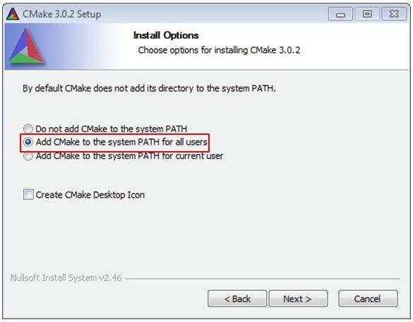
Download CMake 3.0.x from CMake
-
Install CMake, ensuring that the option "Add CMake to system PATH" is selected when installing. It's up to the user to select whether it's installed into the PATH for all users or just the current user. In this example, the assumption is that it's installed for all users.
-
Follow the remaining instructions of the installer.
-
You may need to reboot your system for the PATH changes to take effect.
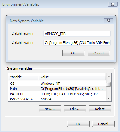
Add a New Environment Variable for ArmGCC_DIR
Create a new system environment variable and name it ArmGCC_DIR. The value of this variable should point to the Arm GCC Embedded tool chain installation path, which, for this example, is:
C:\Program Files (x86)\GNU Tools Arm Embedded\4.9 2015q3Reference the installation folder of the GNU Arm GCC Embedded tools for the exact path name of your installation.
Install CMake
Build an Example Application
To build an example application, follow these steps.
-
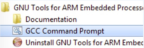
If not already running, open a GCC Arm Embedded tool chain command window. To launch the window, from the Windows operating system Start menu, go to “Programs -> GNU Tools Arm Embedded <version>” and select “GCC Command Prompt”. </version>
-
Change the directory to the example application project directory, which has a path like this:
<install_dir >/boards/<board_name >/<example_type>/<application_name>/armgcc</application_name>
</example_type></board_name ></install_dir >
For this guide, the exact path is:
<install_dir>/boards/evkmimxrt1020/demo_apps/hello_world/armgcc</install_dir>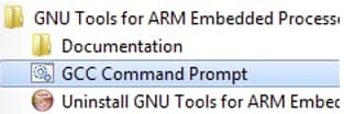
-
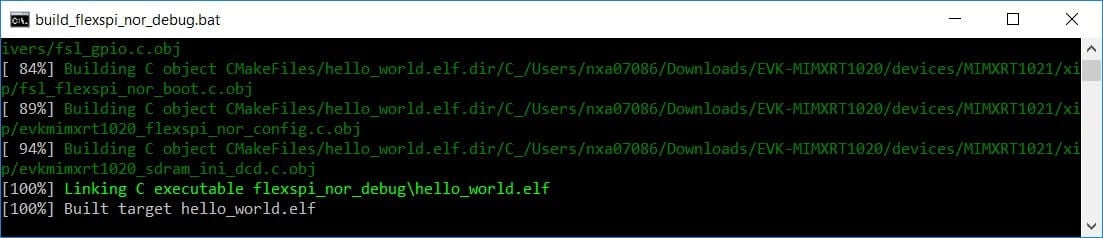
Type “build_flexspi_nor_debug.bat” on the command line or double click on the "build_flexspi_nor_debug.bat" file in Windows operating system Explorer to perform the build. The output is shown in this figure:
Run an Example Application
This section describes steps to run a demo application using J-Link GDB Server application. To perform this exercise, two things must be done:
Make sure that either:
-
The OpenSDA interface on your board is programmed with the J-Link OpenSDA firmware. If your board does not support OpenSDA, then a standalone J-Link pod is required.
You have a standalone J-Link pod that is connected to the debug interface of your board. Note that some hardware platforms require hardware modification in order to function correctly with an external debug interface.
After the J-Link interface is configured and connected, follow these steps to download and run the demo applications:
-
This board supports the J-Link debug probe. Before using it, install SEGGER software, which can be downloaded from SEGGER
-
Connect the development platform to your PC via USB cable between the OpenSDA USB connector and the PC USB connector. If using a standalone J-Link debug pod, also connect it to the SWD/JTAG connector of the board.
-
Open the terminal application on the PC, such as PuTTY or TeraTerm, and connect to the debug serial port number. Configure the terminal with these settings:
-
115200 baud rate, (reference BOARD_DEBUG_UART_BAUDRATE variable in board.h file)
No parity
8 data bits
1 stop bit
-
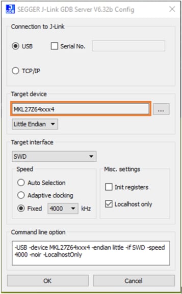
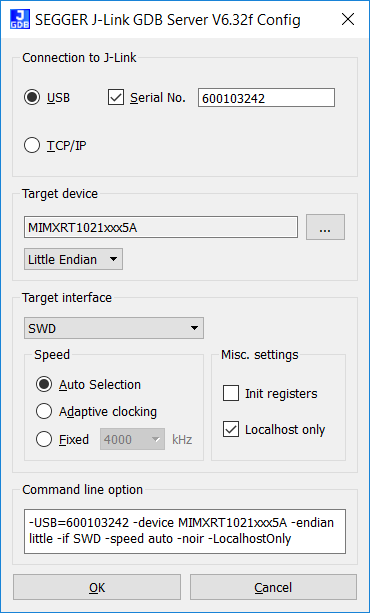
Open the J-Link GDB Server application. Go to the SEGGER install folder, for example, C:\Program Files (x86)\SEGGER\JLink_V632f. Open the command windows here, for Debug and Release targets, and use the command "JLinkGDBServer.exe". Note: for the sdram_debug and sdram_release targets, use the command:
JLinkGDBServer.exescriptfile<install_dir>/boards/evkmimxrt1020/demo_apps/hello_world/ evkmimxrt1020_sdram_init.jlinkscript</install_dir> -
The target device selection chosen for this example is the MIMXRT1021xxx5A.
-
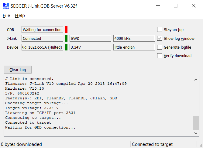
After it is connected, the screen should resemble this figure:
-
If not already running, open a GCC Arm Embedded tool chain window. To launch the window, from the Windows operating system Start menu, go to “Programs -> GNU Tools Arm Embedded <version>” and select “GCC Command Prompt”.</version>
-
Change to the directory that contains the example application output. The output can be found in using one of these paths, depending on the build target selected:
<install_dir >/boards/<board_name >/<example_type>/<application_name>/armgcc/debug</application_name> </example_type></board_name>
</install_dir >
<install_dir >/boards/<board_name >/<example_type>/<application_name>/armgcc/release</application_name> </example_type></board_name ></install_dir >For this example, the path is:
<install_dir>/boards/evkmimxrt1020/demo_apps/hello_world/armgcc/flexspi_nor_debug</install_dir> -
Run the command “arm-none-eabi-gdb.exe <application_name>.elf”. For this example, it is “arm-none-eabi-gdb.exe hello_world.elf”.</application_name>
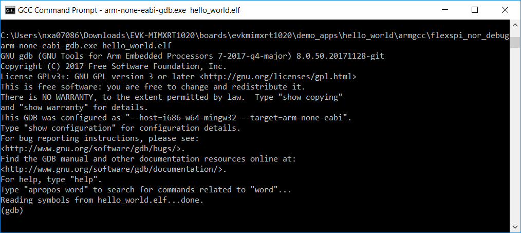
-
Run these commands:
"target remote localhost:2331"
"monitor reset"
"monitor halt"
"load"
- The application is now downloaded and halted at the reset vector. Execute the “monitor go” command to start the demo application.
The hello_world application is now running and a banner is displayed on the terminal. If this is not true, check your terminal settings and connections.
Boot Options
The i.MX RT family supports a number of different boot sources, and includes the option for memory to be copied to an on-chip or external destination memory as well as Execute in Place (XIP) for some interfaces. Learn more about your choices and which one is best for your design.
Boot Options for i.MX RT Crossover MCUs
| Documents and Videos | Description |
|---|---|
| AN12108 How to Enable Boot from QSPI Flash | This document describes how to use Flashloader step by step to program a bootable image into the external storage device either by using Open SDA or MfgTool. |
| AN12107 How to Enable Boot from Octal SPI Flash and SD Card | This document describes how to program a bootable image into the external storage device. |
Tools and References
MCUXpresso Secure Provisioning Tool A GUI-based application provided to simply generation and provisioning of bootable executables on NXP i.MX RT.
Community Resources for Booting Look for answers to your boot questions or submit new questions in our Community.
External Memory
| Documents and Videos | Description |
|---|---|
| AN12437 i.MX RT Series Performance Optimization | How to optimize the system performance running on different memory devices. |
| AN12108 How to Enable Boot from QSPI Flash | This document describes how to use Flashloader step by step to program a bootable image into the external storage device either by using Open SDA or MfgTool. |
| AN12107 How to Enable Boot from Octal SPI Flash and SD Card | This document describes how to program a bootable image into the external storage device. |
| AN12183 How to Enable Debugging for FLEXSPI NOR Flash | This application note describes how to program, debug and configure a new FLEXSPI NOR flash. |
| Developing Code Using the Adesto EcoXip Memory | Learn about the hardware and software requirements for configuring the NXP i.MX RT1050 EVKB board with an Adesto EcoXiP Flash device. |
| AN12564 Implement Read While Write (RWW) on i.MX RT Series | How to implement RWW requirement on the i.MX RT series. |
| AN12239 How to Enable HyperRAM with i.MX RT | How to use the HyperRAM with the i.MX RT MCU, including hardware connections, HyperRAM protocol, source code and performance. |
| AN13028 Advanced HyperRAM/PSRAM Usage on i.MX RT | This application note describes the advanced usage of HyperRAM/PSRAM when used with FlexSPI on i.MX RT MCU, including FlexSPI prefetch function, HyperRAM/PSRAM refresh interval and HyperRAM devices supported. |
MCUXpresso SDK Examples
Several examples, demos and drivers are available within the SDK to help you get started. Some common examples for external memory are listed below.
FlexSPI Nor Polling Example
How to use the FlexSPI driver with polling.
Path:
<SDK_PATH>/boards/evkbimrt1020/driver_examples/flexspi/nor/polling_transferEDMA Transfer Example
Multiple data transfer examples using EDMA.
Path:
<SDK_PATH>/boards/evkbimrt1020/driver examples/flexspi/nor/edma_transferSDRAMC Example
How to use the SEMC controller driver to initialize the external SDRAM chip.
Path:
<SDK_PATH>/boards/evkbimrt1020/driver_examples/semc/sdramTools and References
MCUXpresso Secure Provisioning Tool A GUI-based application provided to simply generation and provisioning of bootable executables on NXP i.MX RT.
Security and Integrity
The i.MX RT1020 is secure-by-design and supported by secure software driving the secure System on a Chip (SoC).
| Documents and Videos | Description |
|---|---|
| i.MX RT Secure Boot Lab Guide | Learn how to use the secure boot features of the i.MX family including generating key pairs and certificates, programming fuses using leftosb tool and signing firmware. |
| Secure Boot on the i.MX RT10xx Crossover MCUs | Learn more about secure boot features and how the MCUXpresso Secure Provisioning Tool allows you to configure them. |
| Getting Starting with MCUXpresso Secure Provisioning Tool | This series of videos covers the basic getting started aspects of the tools with a live demonstration of the tool showcasing a variety of provisioning types and boot devices available on the i.MX RT1060 evaluation kit. |
| Secure Boot Webinar and demo | Using the latest NXP software and tools, you can integrate boot authentication and encrypted execution into your design based on i.MX RT10xx MCUs. Learn more about secure boot features and how the MCUXpresso Secure Provisioning Tool allows you to configure them. |
| Realizing Today’s Security Requirements: Achieving End-To-End Security with a Crossover Processor | Learn about common shared security goals that IoT end and edge nodes should meet, as well as the steps, tools and procedures needed to achieve root of trust in end devices. |
| AN12800 i.MX RT10xx Fuse Provisioning for Security | For secure applications, there are some fuses that are not related to security features and might need to be configured. This document discusses fuse provisioning for secure applications and provides fuse configuration recommendations. |
| AN12419 Secure JTAG for i.MX RT10xx | This document discusses how the Secure JTAG on the i.MX RT10xx MCU family can be used. |
| AN12901 DCP – How to do Key Management | The i.MX RT10xx provides a Data Co-Processor (DCP) block, which supports Advanced Encryption Standard (AES) encryption and hashing functions. This application note describes how to use the AES block with different keys, and how to manage keys. |
MCUXpresso SDK Examples
Several examples, demos and drivers are available within the SDK to help you get started. Some common examples related to security and integrity are listed below.
DCP Example
A demonstration program that uses the KSDK software to implement several cryptography algorithms using the DCP software driver.
Path:
<SDK_PATH>/boards/evkbimrt1020/driver_examples/dcpBEE Example
Demonstrates how to setup BEE driver for on the fly decryption of data stored in QSPI memory region.
Path:
<SDK_PATH>/boards/evkbimrt1020/driver_examples/beeMbedtls Examples
Program performs cryptographic algorithm benchmarking and testing. (Requires optional mbedTLS middleware package).
Path:
<SDK_PATH>/boards/evkbimrt1020/mbedtls_examples/Tools and References
One-stop secure boot tool: NXP-MCUBootUtility A GUI tool specially designed for NXP MCU secure boot. It includes all the features of NXP’s official security enablement toolset with support for full graphical user interface operation.
MCUXpresso Secure Provisioning Tool A GUI-based application provided to simply generation and provisioning of bootable executables on NXP i.MX RT.
Wired Communications
| Documents and Videos | Description |
|---|---|
| Wired Communications Middleware for NXP Microcontrollers | Learn about wired communications libraries and examples provided through MCUXpresso SDK. |
| CANopen in NXP’s MCUXpresso SDK | How to use the EmSA CANopen libraries included with the NXP MCUXpresso SDK. |
| CANopen and Embedded Wizard Demo featuring the i.MX RT 1064 and LPC55 | A demo combining different middleware components of the NXP MCUXpresso SDK using the i.MX RT1064 and LPC55S16 demo boards. |
| AN12822 Emulating 8080 Bus with the FlexIO on RT1050 | How to use the FlexIO module to emulate the 8080 parallel bus and to drive a graphic TFT LCD with the 8080 bus interface. |
| AN12679 Implement High-Speed RS-485 Application with i.MX RT Based on NXP SDK | How to implement RS-485 communication with NXP i.MX RT series EVK, and how to design software based on NXP MCUXpresso SDK. |
| MCU Tech Minutes | Getting Started with CANopen and MCUXpresso | Learn how to download an SDK that includes EmSA's CANopen stacks and set up one manager and one device CANopen network. |
MCUXpresso SDK Examples
Several examples, demos and drivers are available within the SDK to help you get started. Some common examples related to wired communications are listed below.
CANopen Examples
Implements a minimal CANopen Manager and CiA 401 generic I/O device. (Requires optional CANopen middleware package).
Path:
<SDK_PATH>/boards/evkbimrt1020/canopen_examples/Lwip Examples
Various demos and examples for the lwIP TCP/IP stack, which uses the ICMP protocol. (rRquires optional lwIP middleware package).
Path:
<SDK_PATH>/boards/evkbimrt1020/lwip_examples/USB Examples
A number of USB examples for host and device operation exist within the SDK. (Requires optional USB Host, Device, OTG stack middleware package).
Path:
<SDK_PATH>/boards/evkbimrt1020/usb_examples/AWS Ethernet Examples
Amazon FreeRTOS Qualification (AFQ), device configuration, AWS Greengrass discovery, remote control by Android mobile application and shadow lightbulb demos.
Path:
<SDK_PATH>/boards/evkbimrt1020/aws_examplesTools and References
Accelerate Development of Robust Network Communications with CANopen and CANopen FD NXP has partnered with EmSA to offer CANopen as an enablish software technology. Fully integrated CANopen Libraries based on MicroCANopen Plus v7.0 are available in the MCUXpresso SDK.
Wireless Connectivity
Wireless Connectivity
| Documents and Videos | Description |
|---|---|
| Cloud Connectivity on NXP Microcontrollers | Integrated support for cloud services including Amazon Web Services, Microsoft Azure and Google Cloud IoT. |
| AN12257 IoT Device Secure Connection with LoRa | This document explains how to establish IoT secure connection with LoRa between gateway and end devices. |
| i.MX RT and Wi-Fi Solutions from NXP and Panasonic | Take a look at i.MX RT crossover MCUs and the supporting Wi-Fi® modules available, including the dual-band PAN9026 Wi-Fi 4 + Bluetooth™ 5.0 radio module. |
Power Management
Power management includes device-specific techniques and information on power management and low-power optimization.
| Documents and Videos | Description |
|---|---|
| AN12085 How to use i.MX RT Low Power Feature | Describes the low-power application design points on the i.MX RT series. |
| AN12204 Power Consumption and Measurement of i.MX RT1020 | This document discusses the power consumption of the i.MX RT1050 including run mode and low-power mode configurations and power consumption under different power modes. |
MCUXpresso SDK Example
Several examples, demos and drivers are available within the SDK to help you get started. A common examples related to power management is listed below.
Power Mode Switch Demos
Demonstrates the use of power modes in the KSDK for bare metal or RTOS.
Path:
<SDK_PATH>/boards/evkbimrt1020/demo_apps/power_mode_switchAudio
| Documents and Videos | Description |
|---|---|
| Audio Software on NXP Microcontrollers | Middleware, example applications, MCUXpresso Config tools and partner solutions for advanced audio applications. |
| AN12090 Using Multi-Channel Feature of SAI | This document introduces the technology of a 7.1 surround sound system, including SAI and FLAC, and provides guidance on how to use the multi-channel SAI feature to develop applications running in a correct high-performance way. |
MCUXpresso SDK Examples
Several examples, demos and drivers are available within the SDK to help you get started. Some common examples related to motor control are listed below.
SAI Demo
Demonstrates complicated digital audio playback and record case.
Path:
<SDK_PATH>/boards/evkbimxrt1020/demo_apps/saiSAI Peripheral Demo
Demonstrates complicated digital audio playback and record case.
Path:
<SDK_PATH>/boards/evkbimxrt1020/demo_apps/sai_peripheralSAI Driver Examples
How to use sai driver with EDMA, interrupt, record and playback features.
Path:
<SDK_PATH>/boards/evkbimxrt1020/driver_examples/saiI2S Demos
How to use flexio_i2s driver with EDMA and with interrupt.
Path:
<SDK_PATH>/boards/evkbimxrt1020/driver_examples/flexio/i2sUSB Audio Examples
Audio recording and playback examples for bare metal and FreeRTOS.
Path:
<SDK_PATH>/boards/evkbimxrt1020/usb_examplesVoice
| Documents and Videos | Description |
|---|---|
| Voice Processing | A range of voice control and communication software and solutions from NXP, including free voice recognition technology. |
| AN13065 Gender Voice Recognition with TensorFlow Lite Inference | This document describes the steps to train the TensorFlow model on Gender voice audio samples and classification. |
| AN12975 MCU Alexa Voice Solution Support for AzureWave AW-NM372SM WiFi/BT | How to modify the SLN-ALEXA-IOT hardware and software to support AzureWave AW-NM372SM IEEE802.11b/g/n W-LAN and Bluetooth module. |
Tools and References
NXP EdgeReady MCU-Based Solution for Alexa Voice Service This solution leverages the i.MX RT crossover MCU and enables developers to quickly and easily add Alexa voice assistant capabilities to their products.
Motor Control
Motor control is a complicated and advanced topic, with a wide range of intricacies and pitfalls that depend on the number of motors, motor type and sensored or sensorless motor drivers.
NXP has a number of ready-to-use motor control algorithms (middleware), and the best way to get started is with the FreeMaster examples included in the MCUXpresso SDK. These examples utilize the FreeMASTER Run-Time Debugging Tool, a user-friendly real-time debug monitor and data visualization tool that enables runtime configuration and tuning of embedded software applications.
FreeMASTER supports non-intrusive monitoring of variables on a running system and can display multiple variables on oscilloscope-like displays as standard widgets (gauges, sliders and more) or as data in text form, offering simple-to-use data recorders. It can link with HTML, MATLAB® or Excel to other scriptable frameworks or even popular visual programming tools like Node-RED.
| Documents and Videos | Description |
|---|---|
| Get Your Motor Spinning with i.MX RT | This presentation covers the MCU requirements, motor control basics and framework to spin a BLDC, PMSM or ACIM motor and how to implement motor control on the i.MX RT. |
| AN12214 PMSM Field-Oriented Control on MIMXRT10xx EVK | Describes the implementation of the sensor and sensorless speed and position motor control software for 3-phase Permanent Magnet Synchronous Motors (PMSM). |
| PMSM Field-Oriented Control on MIMXRT10xx EVK User’s Guide | Step-by-step guide on how to open, compile, debug and run Permanent Magnet Synchronous Motor (PMSM) projects in most common IDEs, as well as how to turn the NXP Freedom PMSM power stage and the i.MX RT10xx evaluation kit into a complete motor control reference design. |
| AN12659 NXP quad motor-control development platform HW overview | Describes the NXP quad motor-control development platform modular architecture and provides a detailed hardware description of the different components. |
| AN12200 Dual FOC Servo Motor Control on i.MX RT | Describes the dual servo demo with the NXP i.MX RT1020 processor. You can use it as a reference for motor control application developing based on other i.MX RT products. |
| FreeMASTER How To | A starting guide for engineers using FreeMASTER tool. |
| FreeMASTER 3.0 Installation Guide | This article will walk you through the installation process of FreeMASTER 3.0. |
| FreeMASTER Four-Part Webinar Series | On-demand training provides an overview of the FreeMASTER software, its features, capabilities, available examples, application use cases and how to easily get started. |
MCUXpresso SDK Examples
Several examples, demos and drivers are available within the SDK to help you get started. Some common example related to motor control are listed below.
ACIM
AC induction motor middleware.
Path:
<SDK_PATH>/middleware/acimBLDC
Brushless DC electric motor middleware.
Path:
<SDK_PATH>/middleware/bldcFreemaster
Freemaster middleware for motor control examples.
Path:
<SDK_PATH>/middleware/freemasterPMSM
Permanent magnet synchronous motor middleware.
Path:
<SDK_PATH>/middleware/pmsmTools and References
RTCESL Libraries A group of algorithms ranging from basic mathematics operations to advanced transformations and observers, which can be easily incorporated into complex real-time control applications and used in our motor control reference designs.
AMCLIB User’s Guide Describes the Advanced Motor Control Library (AMCLIB) and optimized functions for the family of Arm Cortex M7F core-based microcontrollers.
Quad Motor Control Development Platform Shows how a single i.MX RT1050 Crossover MCU can control up to four different motors, while managing wired or wireless connectivity and an HMI interface.
Tera Term Tutorial
Tera Term Tutorial
Tera Term is a very popular open source terminal emulation application. This program can be used to display information sent from your NXP development platform's virtual serial port.
- Download Tera Term from SourceForge. After the download, run the installer and then return to this webpage to continue.
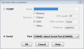
- Launch Tera Term. The first time it launches, it will show you the following dialog. Select the serial option. Assuming your board is plugged in, there should be a COM port automatically populated in the list.
- Configure the serial port settings (using the COM port number identified earlier) to 115200 baud rate, 8 data bits, no parity and 1 stop bit. To do this, go to Setup -> Serial Port and change the settings.
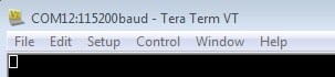
- Verify that the connection is open. If connected, Tera Term will show something like below in it's title bar.
- You're ready to go
PuTTY Tutorial
PuTTY Tutorial
PuTTY is a popular terminal emulation application. This program can be used to display information sent from your NXP development platform's virtual serial port.
- Download PuTTY using the button below. After the download, run the installer and then return to this webpage to continue.
- Launch PuTTY by either double clicking on the *.exe file you downloaded or from the Start menu, depending on the type of download you selected.
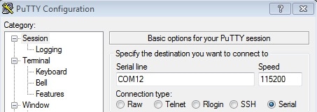
- Configure In the window that launches, select the Serial radio button and enter the COM port number that you determined earlier. Also enter the baud rate, in this case 115200.
- Click Open to open the serial connection. Assuming the board is connected and you entered the correct COM port, the terminal window will open. If the configuration is not correct, PuTTY will alert you.
- You're ready to go
Design Resources
Board Documents
Chip Documents
Support
Training
To learn what to do next, find your issue below. If you still need help, contact NXP Support.
| Training | Description |
|---|---|
| Basic Application Development Using MCUXpresso IDE and MCUXpresso Config Tools | This three-part video series covers the basic interactions between the MCUXpresso IDE and Config Tools when working with either an imported SDK example project or creating a new one. |
| MCU Tech Minute- Key Features and Benefits of the i.MX RT series | Short video presentations introduce some of the key features and benefits of the i.MX RT series. |
| i.MX RT10xx Training | Full list of on-demand training, how-to videos and webinars from NXP about this product. |
Forums
Connect with other engineers and get expert advice on designing with the i.MX RT10xx on one of our community sites.
Product Forums:
Software Forums:
Sensors
Explore the world with a full assortment of NXP sensor solutions. From accelerometers, pressure sensors, touch sensors and many more, NXP has a sensor solution for your project. Find out more at Sensors
NFC
Near Field Communication is a simple, intuitive technology that lets you interact securely with the world around you with a simple touch. Learn more about NXP’s NFC solutions at NFC
i.MX and MCUXpresso Communities
Connect with other engineers and get expert advice on designing with i.MX processors and MCUXpresso Software and Tools. Join the community discussion in one of our two dedicated communities: i.MX Community or MCUXpresso Software and Tools Community
On this page
- 1.1
Get Started With MIMXRT1020-EVK Development Platform - How to
- 1.2
Attach the USB Cable
- 1.3
Run the Out-of-Box Demo
- 2.1
Choose a Development Path
- 2.2
Installing software for the MIMXRT1020-EVK
- 2.3
Jump Start Your Design with the MCUXpresso SDK
- 2.4
Install Your Toolchain
- 2.5
PC Configuration