Getting Started with the S32K146 Evaluation Board for General Purpose
Contents of this document
-
Out of the Box
-
Get Software
-
Plug It In
-
Build, Run
-
Debug
Sign in to save your progress. Don't have an account? Create one.
Purchase your S32K146EVB-Q144 Evaluation Board for Automotive General Purpose
1. Out of the Box
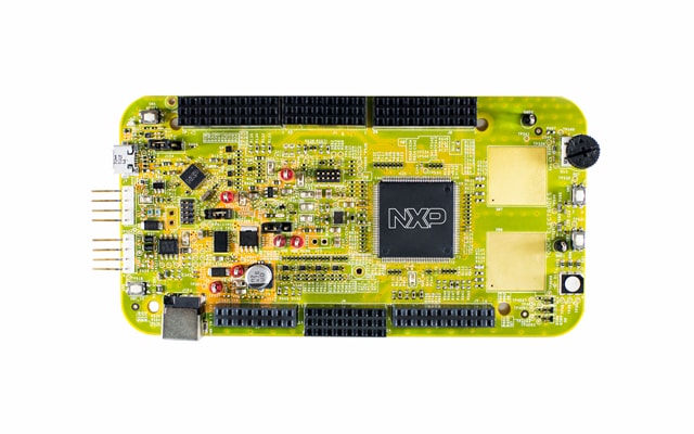
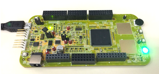
1.1 Get to Know the S32K146EVB-Q144 Evaluation Board for General Purpose
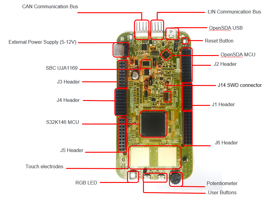
1.2 S32K146EVB-Q144 Evaluation Board Features
- Supports S32K146EVB-Q144 144LQFP
- Small form factor size supports up to n” x n”
- Arduino™ UNO footprint-compatible with expansion “shield” support
- Integrated open-standard serial and debug adapter (OpenSDA) with support for several industry-standard debug interfaces
- Easy access to the MCU I/O header pins for prototyping
- On-chip connectivity for CAN, LIN, UART/SCI
- SBC UJA1169 and LIN phy TJA1027
- Potentiometer for precise voltage and analog measurement.
- RGB LED
- Two push-button switches (
SW2andSW3) and two touch electrodes -
Flexible power supply options
- o microUSB or
- o external 12 V power supply
1.3 Jumper Settings
| Jumper | Configuration | Description |
|---|---|---|
J104 |
1-2 2-3 (Default) |
Reset signal to OpenSDA, use to enter into OpenSDA Bootloader mode. Reset signal direct to the MCU, use to reset S32K146EVB-Q144. |
J107 |
1-2 2-3 (Default) |
S32K146EVB-Q144 powered by 12 V power source. S32K146EVB-Q144 powered by USB micro connector. |
J10 |
1-2 2-3 (Default) |
VDD voltage is connected to 3.3 V. VDD voltage is connected to 5 V. |
1.4 HMI Mapping
| Component | S32K146EVB-Q144 |
|---|---|
| Red LED | PTD15 (FTM0 CH0) |
| Blue LED | PTD0 (FTM0 CH2) |
| Green LED | PTD16 (FTM0 CH1) |
| Potentiometer | PTC14 (ADC0_SE12) |
| SW2 | PTC12 |
| SW3 | PTC13 |
| OpenSDA UART TX | PTC7 (LPUART1_TX) |
| OpenSDA UART RX | PTC6 (LPUART1_RX) |
| CAN TX | PTE5 (CAN0_TX) |
| CAN RX | PTE4 (CAN0_RX) |
| LIN TX | PTD7 (LPUART2_TX) |
| LIN RX | PTD6 (LPUART2_RX) |
| SBC_SCK | PTB14 (LPSPI1_SCK) |
| SBC_MISO | PTB15 (LPSPI1_SIN) |
| SBC_MOSI | PTB16 (LPSPI1_SOUT) |
| SBC_CS | PTB17 (LPSPI1_PCS3) |
2. Get Software
2.1 Integrated Development Environment (IDE)
The S32 Design Studio for Arm® is a complimentary Integrated Development Environment (IDE) for automotive and ultra-reliable Arm-based microcontrollers that enables editing, compiling and debugging of designs.
DOWNLOAD S32DS FOR ARM2.2 Run-Time Debugging Tool
S32K146EVB-Q144 evaluation board performs better when using the FreeMASTER tool for run-time debugging. You can also download and install the FreeMASTER Communication Driver (source code already included in the example project).
DOWNLOAD FREEMASTER TOOL3. Plug It In
3.1 Power Up the Board
-
The S32K146EVB-Q144 evaluation board powers from a USB or external 12 V power supply. By default USB power is enabled with
J107 - Connect USB cable to a PC
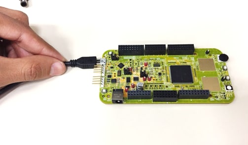
- Allow the PC to automatically configure the USB drivers if needed
- Debug is done using OpenSDA through
J7 - When powered through USB, LEDs
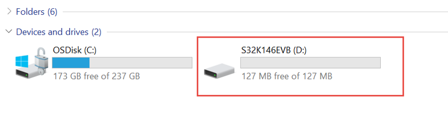
D2andD3should light green - Once the board is recognized, it should appear as a mass storage device in your PC with the name S32K146EVB-Q144
- Board is preloaded with a software, in which the red, blue and green LEDs will toggle at different rates
4. Build, Run
4.1 Flash the Out-of-Box Demo
Download the S32K146EVB_OOBE_FreeMASTER_Firmware.srec from Software and Tools tab . Then drag and drop the downloaded image file into your S32K146EVB-Q144 disk that is listed in your PC window.
4.2 Communicate with Run-Time Debugger
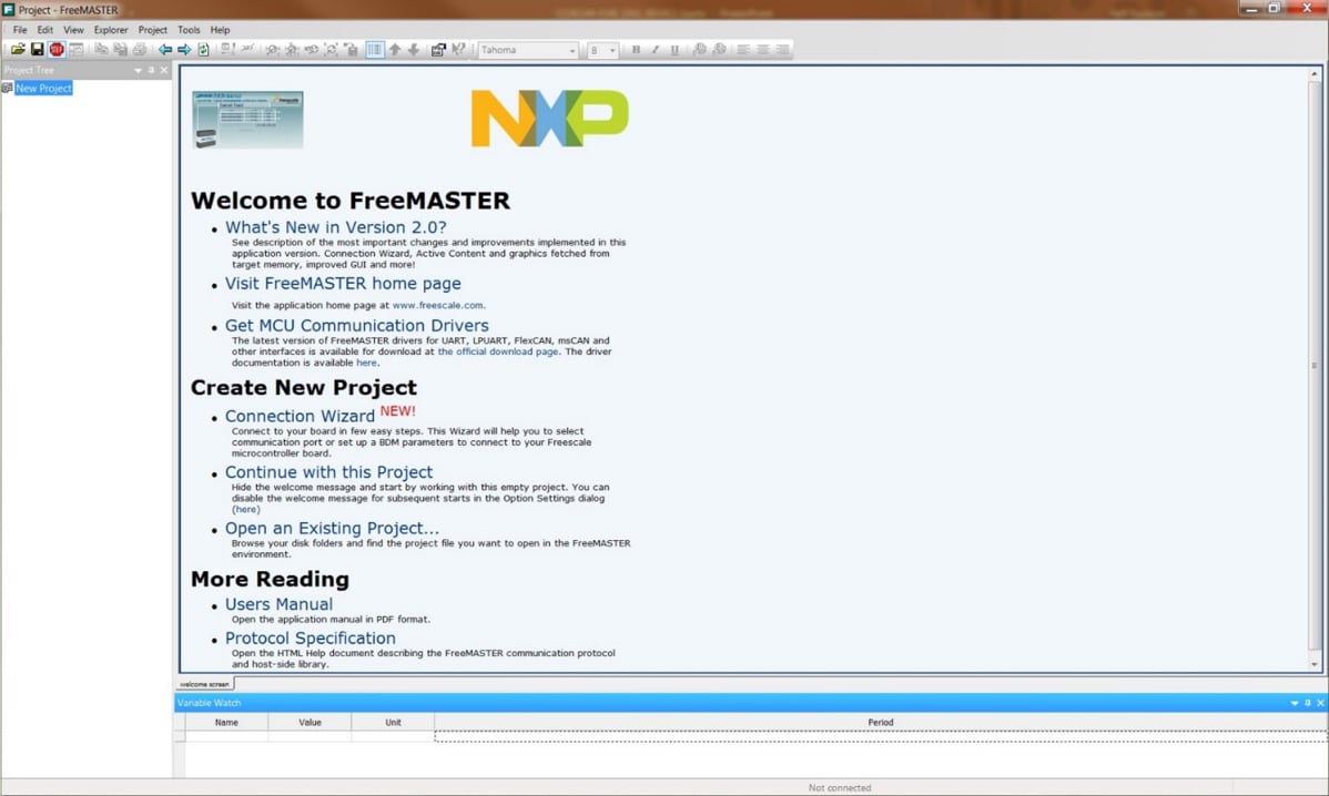
Open the FreeMASTER application on your PC. You should see Welcome page:
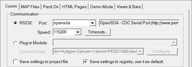
Setup communication port to “opensda” and speed to 115200 b/s:
-
Setup communication manualy:
“Project → Options → Comm"
-
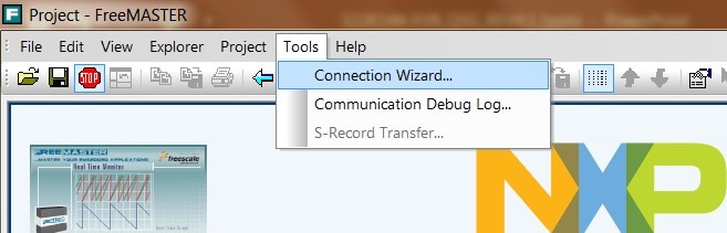
Setup communication automatically:
“Tools → Connection Wizard”
4.3 FreeMASTER JumpStart Project Download
Once the FreeMASTER application detects the web address stored as an TSA active content in the flash memory of the S32K146EVB-Q144 MCU, the download of the FreeMASTER project from NXP Semiconductors will be initiated.
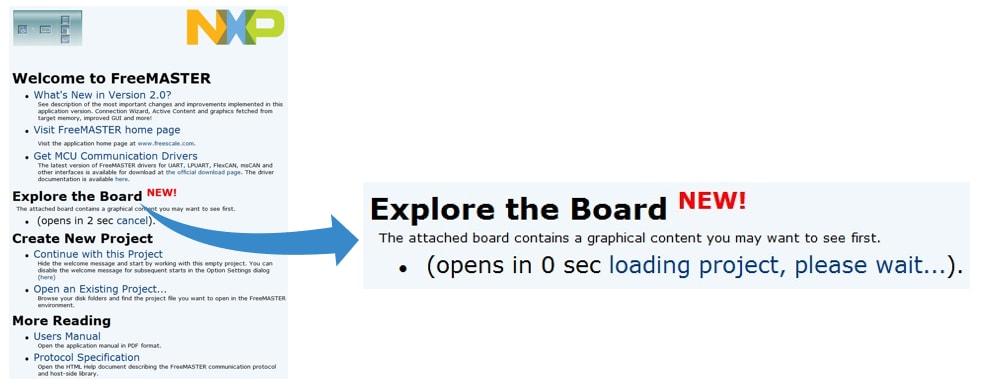
4.4 FreeMASTER JumpStart Project Loaded
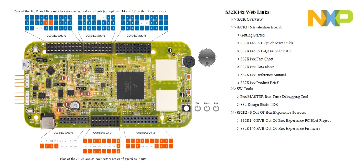
The FreeMASTER JumpStart project description:
4.5 FreeMASTER JumpStart
Display main project panel,
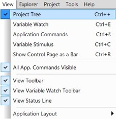
“Project → View → Project Tree“..
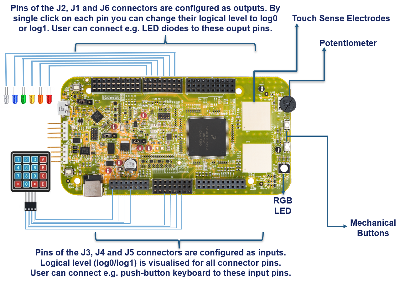
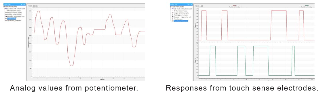
Display real-time oscilloscope graph examples such as
“Potentiometer“ or “Touch Sense Electrodes“.
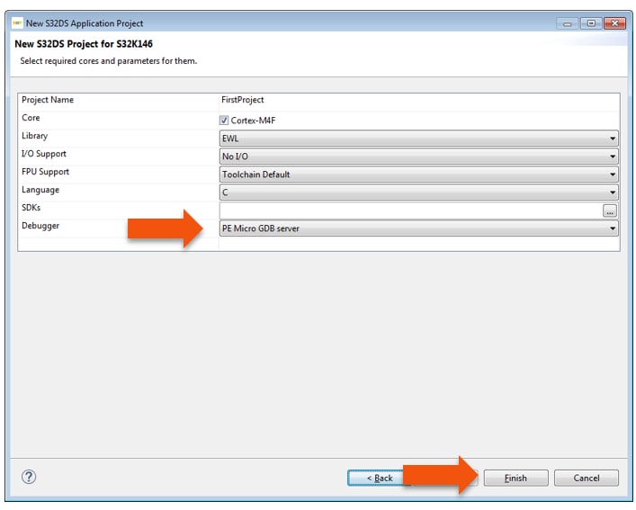
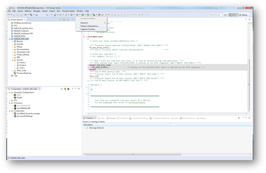
4.6 Create a New Project in S32 Design Studio
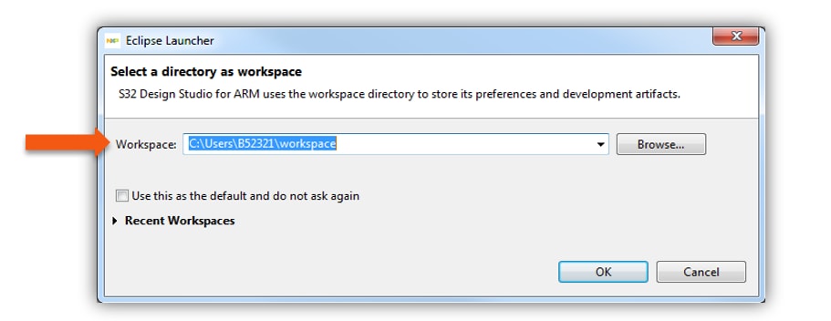
To create a new project for first time at Eclipse Launcher, please follow the following steps:
- Start program: Click on “S32 Design Studio for Arm” icon
- Select workspace:
- Choose default (see below example) or specify new one
- Suggestion: Uncheck the box “Use this as the default and do not ask again”
- Click OK
- Select “File → New → S32DS Application Project”
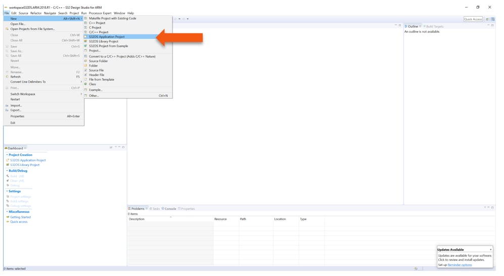
-
Project Name:
- Example: “FirstProject”
-
Project Type:
- Select from inside executable or library folder
- Click on “Next”
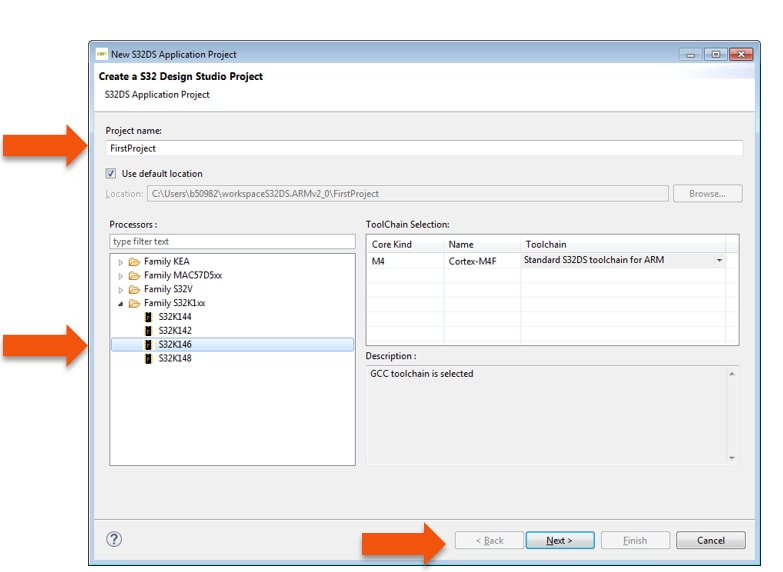
- Select “Debugger → Support and Library/SDKs Support” if needed
- Click “Finish”
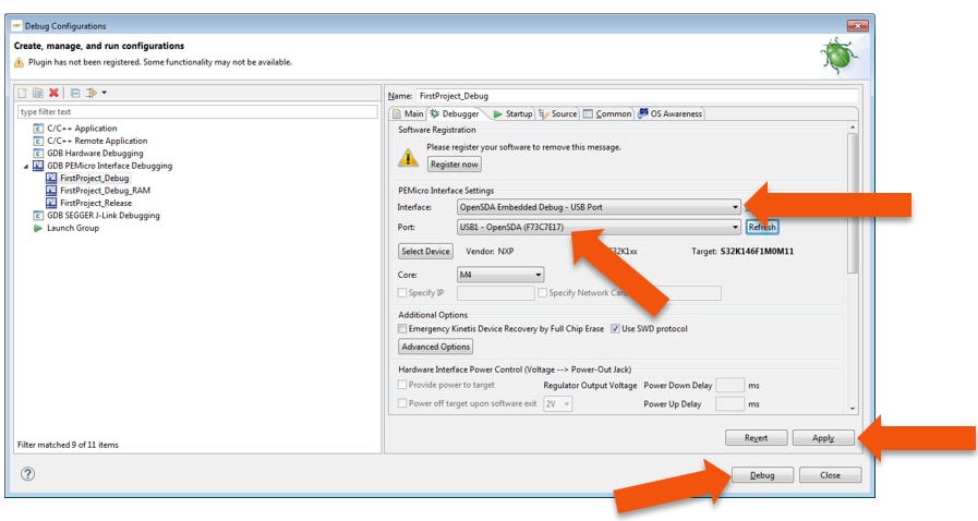
4.7 OpenSDA Configuration
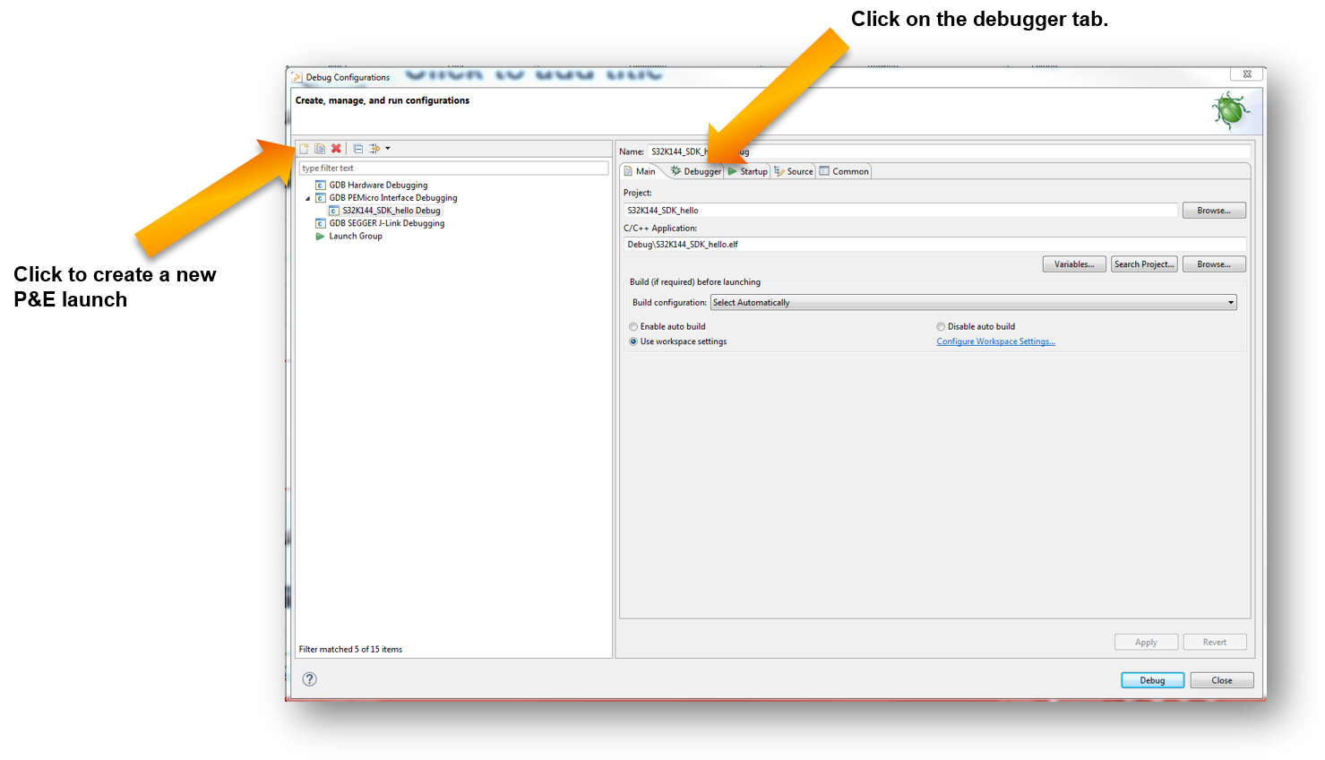
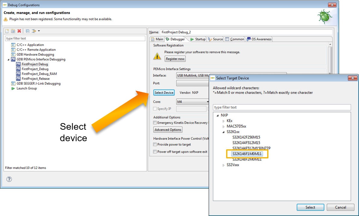
To Debug your project with OpenSDA, it is necessary to select the OpenSDA in the Debug Configuration.
- Select your project, and click on “Debug Configuration”
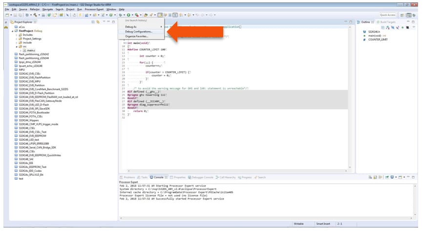
- Select the Debug configuration under “GDB PEMicro Interface Debugging”
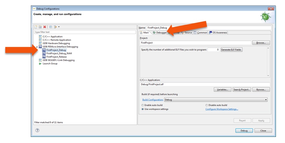
- Click on “Debugger” tab
- Select OpenSDA as the interface, if your board is plugged should appear in the Port field
- Click “Apply” and “Debug” to finish
4.8 Create an Example from SDK
The S32 Design Studio IDE already includes the Software Development Kit for quickly develop applications on S32K1xx devices.
- To create a project using an example go to “File &rarrk New &rarrk S32DS Project from Example”
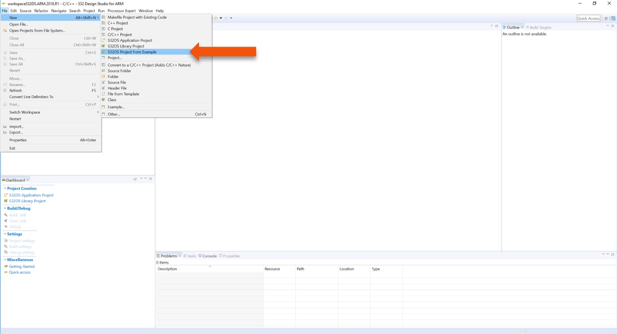
- Go to the “S32K1xx SDK RTM v4.0.1” Example Projects section and select the example that wants to be used
- In this example the “hello_world” is selected
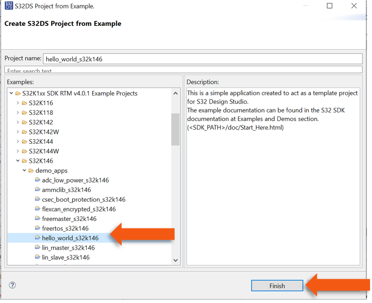
- A new project would be created in the workspace
- Click on “generate code icon” and then on “Debug”, as indicated
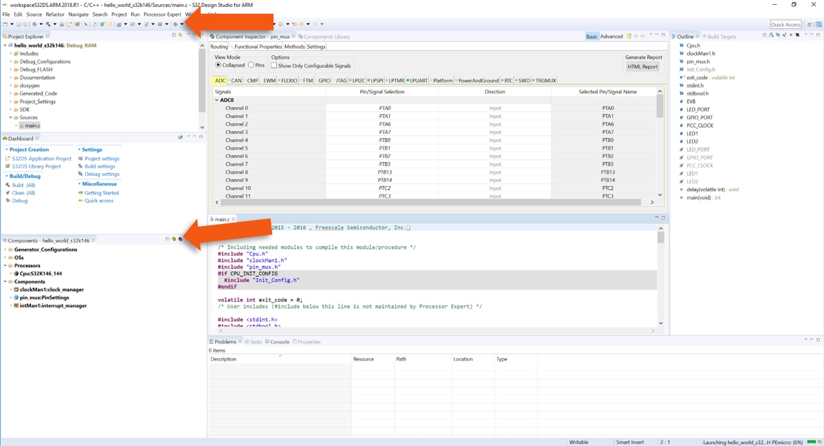
- If run correctly, the LED should start blinking red and green
The complete documentation of the SDK can be found in:
C:\NXP\S32DS_ARM_v2018.R1\S32DS\S32SDK_S32K14x_EAR_0.8.6\doc\Start_here.htmlFor more information about the use of the SDK go click on the following link for an SDK training.
5. Debug
5.1 Debug Basics
Debug configuration is only required once. Subsequent starting of debugger does not require those steps.
Three options to start debugger:
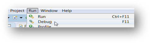
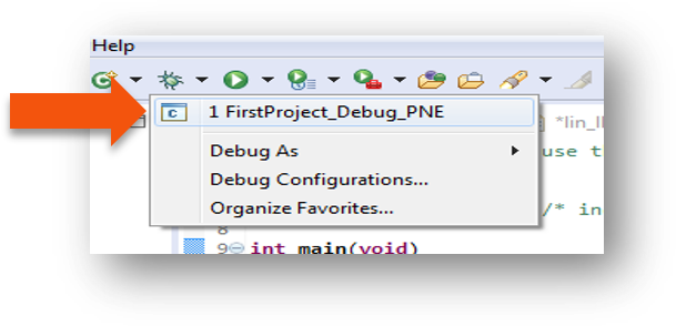
- If the “Debug Configuration” has not been closed, click on “Debug” button on bottom right
- Select Run → Debug (or hit F11)
- Click on pull down arrow for bug icon and select → debug.elf target
5.2 Step, Run, Suspend and Resume
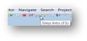
- Step Into (F5)
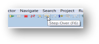
- Step Over (F6)
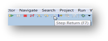
- Step Return (F7)
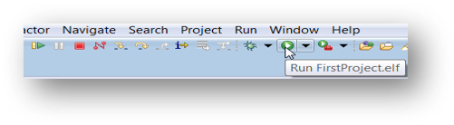
- Run
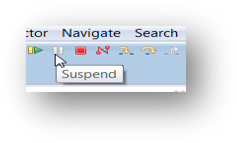
- Suspend
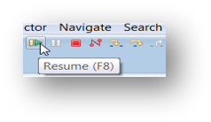
- Resume (F8)
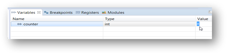
5.3 View and Alter Variables
- View variables in “Variables” tab
- Click on a value to allow typing in a different value
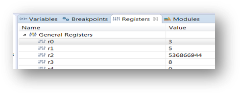
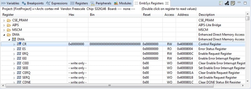
5.4 View and Alter Registers
- View CPU registers in the “Registers” tab
- Click on a value to allow typing in a different value
- View peripheral registers in the EmbSys Registers tab
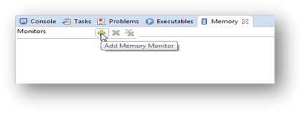
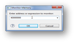
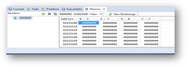
5.5 View and Alter Memory
- Add Memory Monitor
- Select Base Address to Start at: 40000000
- View Memory
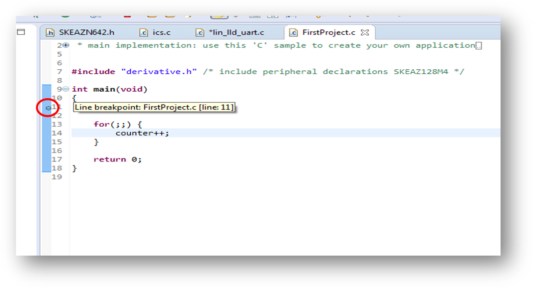
5.6 Breakpoint
Add Breakpoint: Point and Click.
- Light blue dot represents debugger breakpoint
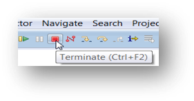
5.7 Reset and Terminate Debug Session
How to reset and terminate debug session:
- Light blue dot represents debugger breakpoint
- Terminate Ctl+F2()
Introduction to OpenSDA
Introduction to OpenSDA
OpenSDA is an open-standard serial and debug adapter. It bridges serial and debug communications between a USB host and an embedded target processor. OpenSDA software includes a flash-resident USB mass-storage device (MSD) bootloader and a collection of Firmware Apps. S32K146EVB-Q144 EVB comes with the MSD Flash Programmer OpenSDA Application preinstalled. Follow these instructions to run the OpenSDA Bootloader and update or change the installed OpenSDA Application.
| Enter OpenSDA Bootloader Mode | Load an OpenSDA Application |
|---|---|
A removable drive should now be visible in the host file system with a volume label of BOOTLOADER |
You are now running the latest version of the MSD flash programmer. Use this same procedure to load other Firmware Apps. |
The MSD Flash Programmer is a composite USB application that provides a virtual serial port and an easy and convenient way to program applications into the S32K146 MCU. It emulates a FAT16 file system, appearing as a removable drive in the host file system with a volume label of S32K146EVB-Q144.
Raw binary and Motorola S-record files that are copied to the drive are programmed directly into the flash of the S32K146 and executed automatically. The virtual serial port enumerates as a standard serial port device that can be opened with standard serial terminal applications.
| Using the MSD Flash Programmer | Using the Virtual Serial Port |
|---|---|
The new application should now be running on the S32K146 EVB. Starting with v1.03 of the MSD Flash Programmer, you can program repeatedly without the need to unplug and reattach the USB cable before reprogramming. Drag one of the |
|
Design Resources
Chip Documents
S32K1xx MCU Family - Data Sheet
S32K1xx MCU Family - Reference Manual
S32K1xx MCU Family - Functional Safety Documentation (requires access to the SafeAssure NDA group)
Support
Forums
Connect with other engineers and get expert advice on designing with the S32K146EVB-Q144 on one of our community sites.
On this page
- 1.1
Get to Know the S32K146EVB-Q144 Evaluation Board for General Purpose
- 1.2
S32K146EVB-Q144 Evaluation Board Features
- 1.3
Jumper Settings
- 1.4
HMI Mapping
- 4.1
Flash the Out-of-Box Demo
- 4.2
Communicate with Run-Time Debugger
- 4.3
FreeMASTER JumpStart Project Download
- 4.4
FreeMASTER JumpStart Project Loaded
- 4.5
FreeMASTER JumpStart
- 4.6
Create a New Project in S32 Design Studio
- 4.7
OpenSDA Configuration
- 4.8
Create an Example from SDK