Getting Started with the EVBMA7X18DT1 Evaluation Board
Contents of this document
-
Out of the Box
-
Get to Know Hardware
-
Configure the Hardware
Sign in to save your progress. Don't have an account? Create one.
Purchase your BMA7X18 Evaluation Board
1. Out of the Box
The NXP analog product development boards provide an easy-to-use platform for evaluating NXP products. The boards support a range of analog, mixed-signal and power solutions. They incorporate monolithic integrated circuits and system-in-package devices that use proven high-volume technology. NXP products offer longer battery life, a smaller form factor, reduced component counts, lower cost and improved performance in powering state-of-the-art systems.
This page guides you through the process of setting up and using the EVBMA7X18DT1 board.
1.1 Kit Contents and Packing List
The EVBMA7X18DT1 contents include:
- Assembled and tested EVBMA7X18DT1 board in an antistatic bag
- Transport protocol link (TPL) cable
- Battery emulator connector cable
2. Get Hardware
2.1 Board Features
- The board implements a resistive divider to allow evolution of the analog front-end (AFE) without cell emulators
- Option to connect to the BATT-18EMULATOR or real cells
- Option to connect cell 0 to an external stimulus
- Easy access to general-purpose input/output (GPIO) pins
- Operation mode indicator
- Components assembly only on the top side
- Compact design
- Minimized BOM
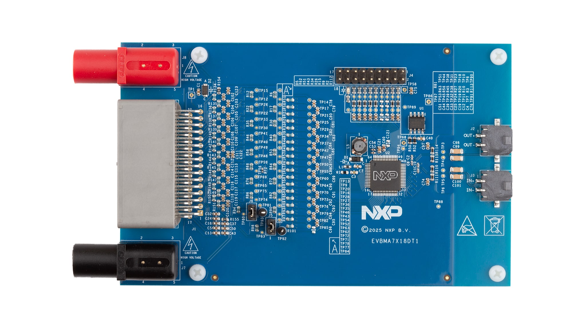
2.2 Board Description
The EVBMA7X18DT1 is an evaluation board for battery cell controller. It comes with one BMA7418 chip, an AFE IC that supports up to 18 cells and includes electrochemical impedance spectroscopy (EIS) functionality. The BMA7418 includes the feature set of the BMA7118, enabling the board to serve as an evaluation platform for both devices.
The board already includes all components needed to run the BMA7418. It can be powered using a DC laboratory power supply, the BATT-18EMULATOR or real battery cells.
3. Configure Hardware
3.1 Configure the Hardware
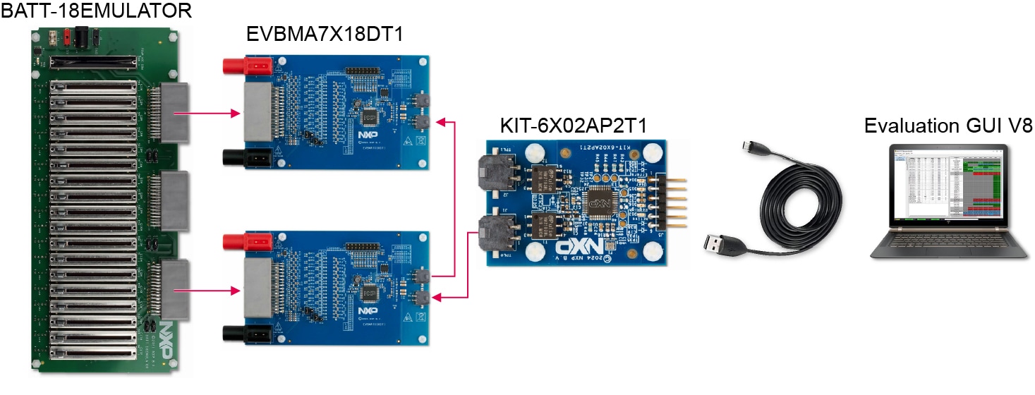
Figure 2 shows a complete setup. The setup uses the BATT-18EMULATOR to supply and emulate the cell voltages for two EVBMA7X18DT1. The KIT6X02AP2T1 enables communication to a regular PC. The evaluation GUI displays the measured voltages and allows interacting with the BMA7X18 devices. Depending on the scope of evaluation, the evaluation system can be altered to use different components (for example, real battery cells or a different TPL communication source).
Design Resources
Board Information
Additional References
In addition to our EVBMA7X18DT1 page, you may also want to visit: