Getting Started with the KITPF5023FRDMEVM
Contents of this document
-
Get Started
-
Get to Know the Hardware
-
Configure the Hardware for Startup
-
Install Software
Sign in to save your progress. Don't have an account? Create one.
Purchase your KITPF5023FRDMEVM | PF5023 Evaluation Board
1. Get Started
The NXP analog product development boards provide an easy-to-use platform for evaluating NXP products. The boards support a range of analog, mixed-signal and power solutions. They incorporate monolithic integrated circuits and system-in-package devices that use proven high-volume technology. NXP products offer longer battery life, a smaller form factor, reduced component counts, lower cost and improved performance in powering state-of-the-art systems.
This page will guide you through the process of setting up and using the KITPF5023FRDMEVM evaluation board.
1.1 Kit Contents/Packing List
The KITPF5023FRDMEVM contents include:
- Assembled and tested KITPF5023FRDMEVM connected to FRDM-KL25Z in an anti-static bag
- 3.0 ft USB-STD A to USB-B-mini cable
- Quick start guide
1.2 Additional Hardware
In addition to the kit contents, the following hardware is necessary or beneficial when working with this kit.
- Power supply with a range of 2.5 V to 6.0 V and current limit set initially to 100 mA
1.3 Windows PC Workstation
This evaluation board requires a Windows PC workstation. Meeting these minimum specifications should produce great results when working with this kit.
- USB-enabled computer with Windows 7 or Windows 10
1.4 Software
Installing software is necessary to work with this evaluation board.
- NXP_GUI_ PR_1.0: software interface GUI, tool to configure OTP, generate TBB and OTP scripts
1.5 User Manual
Refer to UM11374, KITPF5023FRDMEVM evaluation board for additional details on the featured components and board configuration.
2. Get to Know the Hardware
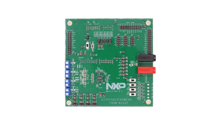
2.1 Board Description
The KITPF5023FRDMEVM evaluation board is the complete evaluation kit of the PF5023 power management IC from NXP Semiconductors. This user guide describes the functionality of the evaluation board, explains how to use the PMIC device in an application environment and gives details about the hardware and software required.
The KITPF5023FRDMEVM board is the dedicated kit for the PF5023 PMIC but it is also compatible with other PMIC devices in the family like the PF5020 and PF5024.
2.2 Board Features
- SW1, SW2, SW3 in single-phase mode (default) or multiphase mode up to 3.5 A peak each
- PWRON switch for global wake-up or enable
- Individual enable control switch for each regulator
- LEDs to indicate individual PGOODx and global PGOOD status
- USB interface through FRDM-KL25Z for register access, TBB mode and OTP programming
- Multiple signal connectors for easy access
- Terminal blocks and test point for all the regulators for easy testing and evaluation
2.3 Board Components
Overview of the KITPF5023FRDMEVM evaluation board
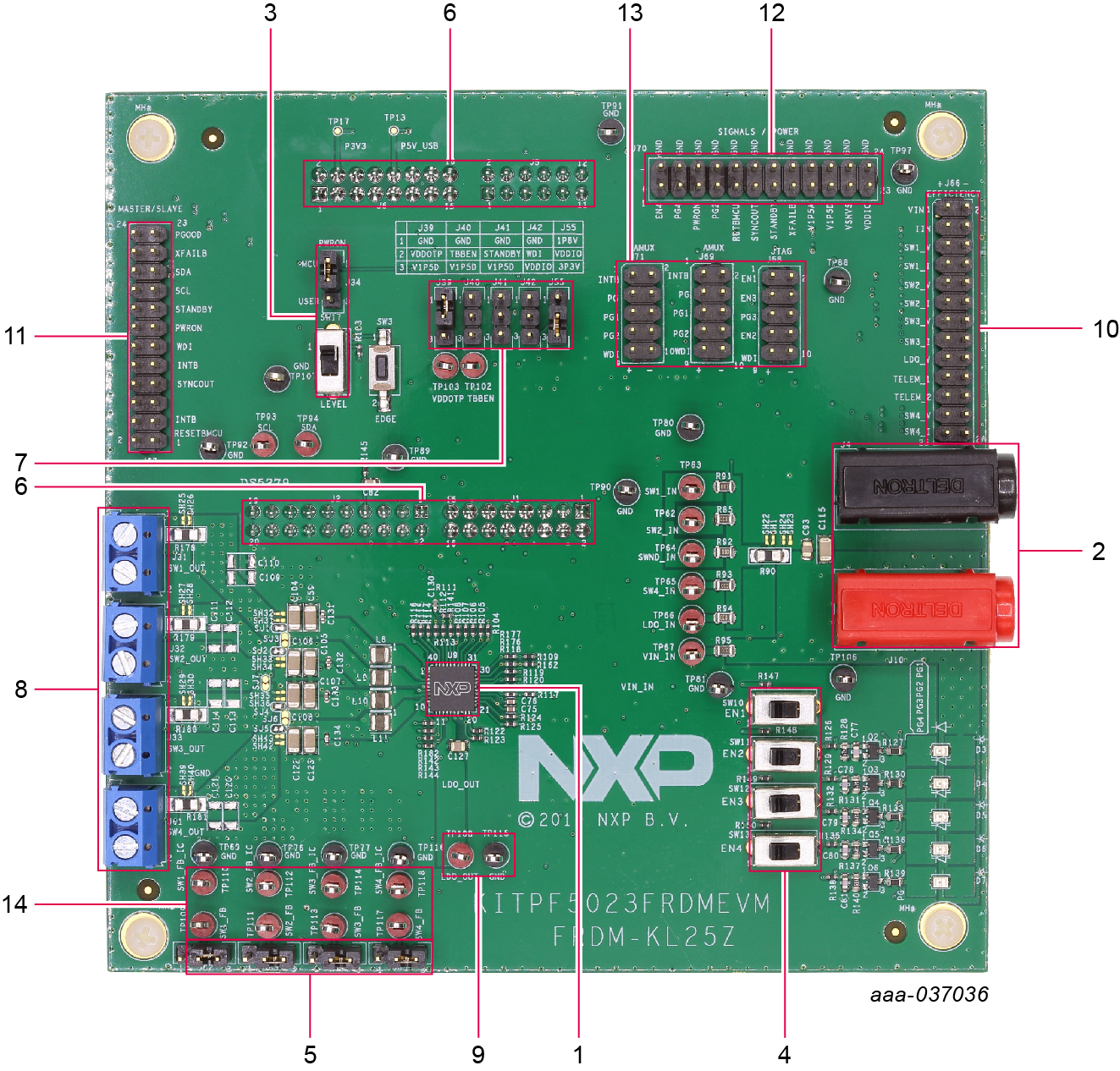
- PF5023 PMIC
- VIN connector
- PWRON control switch and jumper
- Enable switches for the regulators
- Feedback jumpers for the buck regulators
- FRDM-KL25Z connectors (for SW/GUI interface) on the bottom side of the board
- Jumpers for IO control (TBBEN, VDDOTP, STANDBY, WDI, VDDIO)
- Load terminal for the buck outputs
- Load / test point for LDO1 output
- Connector for efficiency measurement
- Connector for leader/follower (multi-PMIC) connection
- Connector for signals and power measurement
- Connectors for IO measurement
- Feedback test points of buck regulators to measure loop stability
2.4 Additional Board Support
Refer to UM11374, KITPF5023FRDMEVM evaluation board user manual for additional details on the featured components.
3. Configure the Hardware for Startup
To configure the hardware and workstation, complete the following procedure:
-
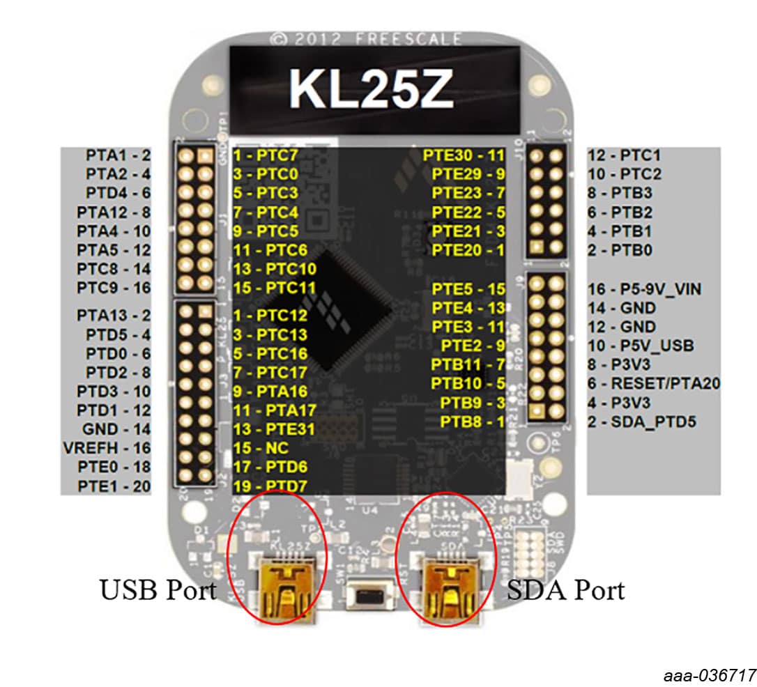
With the USB cable connected to the PC and the USB port in the FRDM board, apply VIN to the evaluation board
- a. Provide external VIN between 2.5 V to 5.5 V on J10 (VIN) and J4 (GND). Make sure that the supply is current limited to 100 mA
- Press Reset on the FRDM board, to ensure board is properly recognized
- If the NXPGUI application was not installed before, perform step 6 of Section 4.2 "FRDM board Bootloader refresh in a Windows 7 or 10 system (optional - only when the FRDM board is not preprogrammed)" to install it for the first time. Open the NXPGUI application from the installation folder or from the Start menu
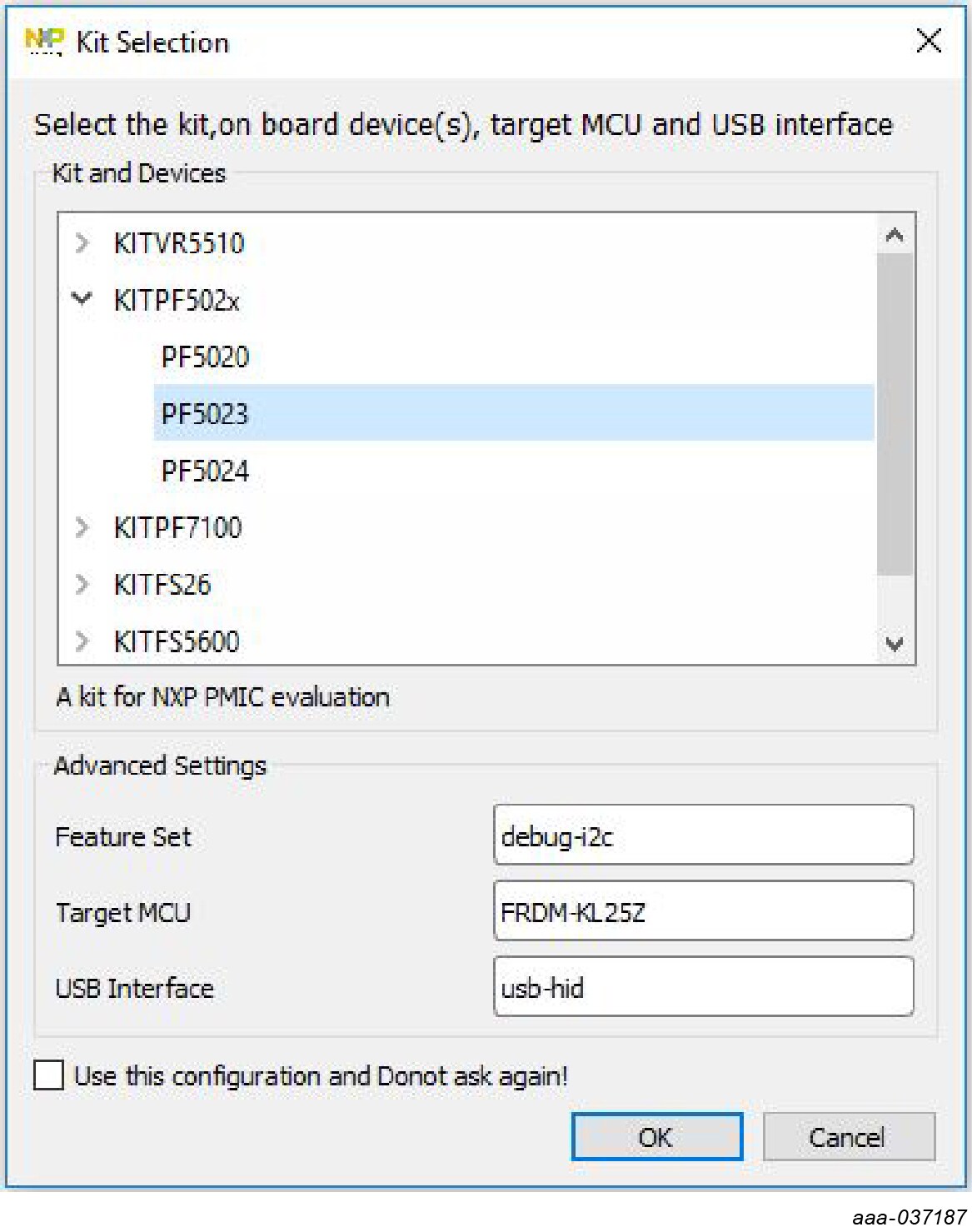
- A configuration window is displayed. Select one of the devices to load the predefined configurations, and then click OK
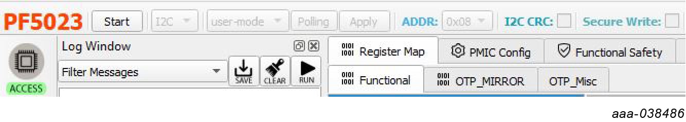
- The NXPGUI interface should open and load the main framework. Make sure to confirm if the GUI can identify the USB device properly. This is displayed by the active Start button on the top-left corner of the GUI. Note: The USB cable should be connected for the GUI to recognize and be able to connect to the device.
- Click Start to enable the connection to the device. The device status can be read from the bottom-left corner of the GUI
- Once the device is connected, the system is ready for Hardwire, TBB or OTP operation as desired
3.1 Additional Board Support
Refer to UM11374, KITPF5023FRDMEVM evaluation board user manual for additional details on the hardware configuration.
4. Install Software
4.1 Installing and Configuring Software and Tools
Download and unzip the NXP_GUI_ PR_1.0 file into any desired location. The package should contain a GUI folder and MCU folder.
4.2 FRDM Board Bootloader Refresh in a Windows 7 or 10 system (Optional Only When the FRDM Board is not Preprogrammed)
- Press the RST push button on the FRDM board and connect the USB cable into the SDA port on the FRDM board. A new Bootloader device should appear on the left pane of the file explorer
- Drag and drop the file MSD-DEBUG-FRDM-KL25Z_Pemicro_v118.SDA from the MCU folder into the Bootloader drive. Note: Make sure to allow enough time for the firmware to be saved in the Bootloader
- Disconnect and reconnect the USB cable into the SDA port (this time without pressing the RST push button). The PC installs a new device called FRDM_KL25
- Locate the file nxp-gui-fw-frdmkl25z-usb_hid-pf502x_v0.1.6.bin from the MCU folder and drag and drop the file into the FRDM_KL25Z device
- FRDM board firmware is successfully loaded
- Open and run the NXP_GUI-1.0-Setup.exe file from the GUI folder inside the unzipped package. This installs the FlexGUI software in the system. Install it in a local destination folder
4.3 Additional Software Support
Refer to UM11374, KITPF5023FRDMEVM evaluation board user manual for additional software details.
4.4 Ready to Use
Start embedded application development.
Design Resources
Additional Resources
Product Summary Page
The product summary page for PF5023 is at PF5023.
Tool Summary Page
The tool summary page for KITPF5023FRDMEVM board is at KITPF5023FRDMEVM.
The page provides overview information, technical and functional specifications, ordering information, documentation and software. The Get Started provides quick-reference information applicable to using the KITPF5023FRDMEVM board, including the downloadable assets.
References
In addition to our PF5023: Power management integrated circuit (PMIC) for high performance applications page, you may also want to visit:
Application pages:
- Automotive Vision Systems
- Mid to High Infotainment / eCockpit
- Entry Infotainment / Connected Radio
- Mid/High-End Infotainment Head Unit
Hardware pages:
Software pages:
Community page:
On this page
- 1.1
Kit Contents/Packing List
- 1.2
Additional Hardware
- 1.3
Windows PC Workstation
- 1.4
Software
- 1.5
User Manual