Getting Started with the OM13094
Contents of this document
-
Plug It In
-
Get Software
-
Build, Run
Sign in to save your progress. Don't have an account? Create one.
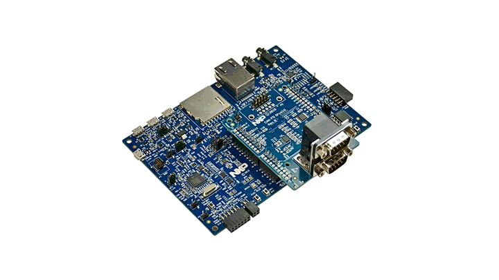
Purchase your LPCXpresso54618 CAN-FD kit
1. Plug It In
Let's take your LPCXpresso54608 board for a test drive! You have the choice of watching the sequence in a short video or following the detailed actions list below.
Get Started with LPCXpresso54608 Development Platform - Demo
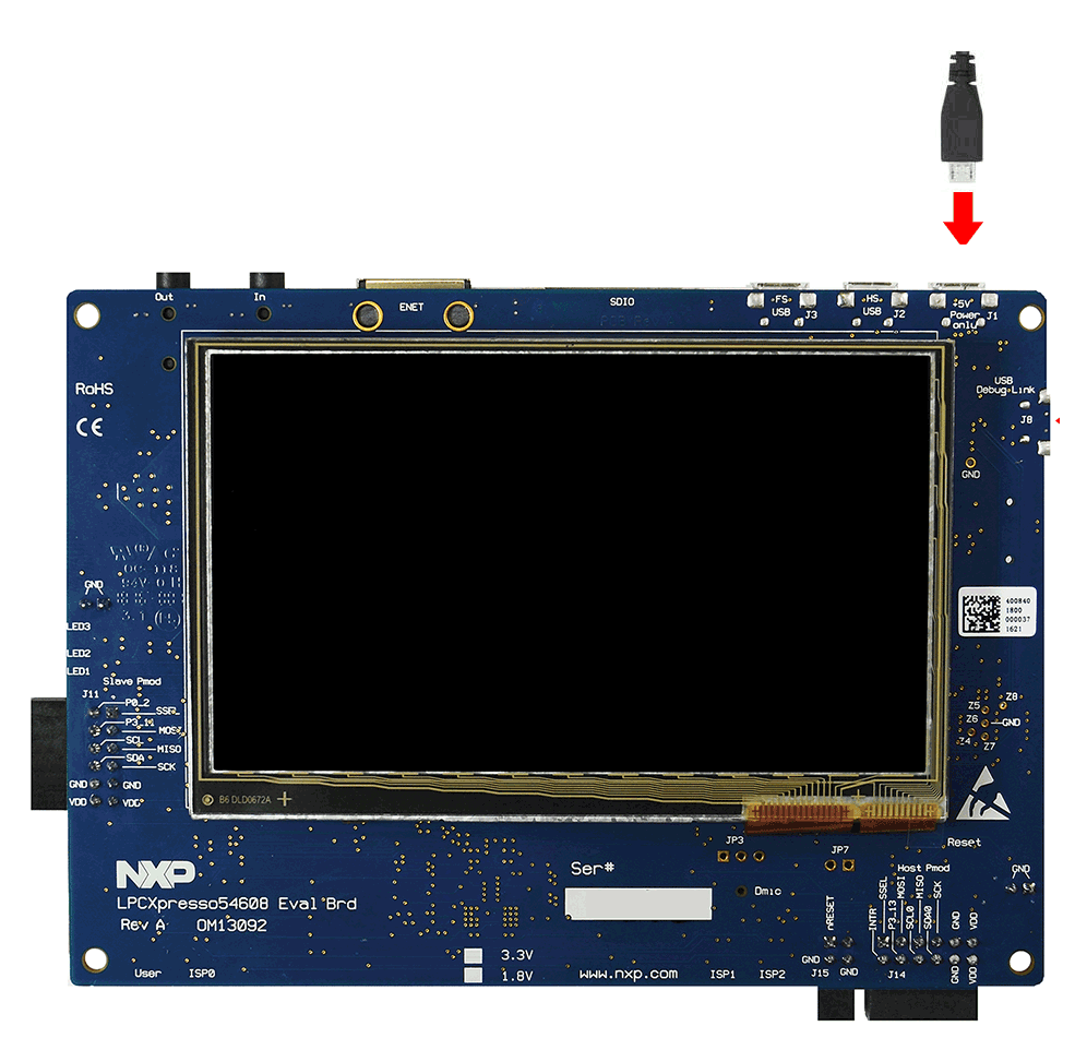
1.1 Attach the USB Cable
1.2 Run the Out-of-Box Demo
Your LPCXpresso54618 CAN-FD kit comes preloaded with a CAN loopback test that attempts to transfer data between the two CAN/CAN-FD ports of the LPC54618 device. As the test runs, LED1 and LED2 light alternately and LED3 lights when the test is complete. If test passes then all these LEDs will stay lit, if it fails then only LED3 will stay on. A female-to-female, straight-through cable need to be connected between the two DB9 connectors of the shield board in order to complete the loopback connection, otherwise the test will fail.
2. Get Software
2.1 Choose a Development Path:
MCUXpresso SDK
- True debug support via SWD and JTAG
- High software flexibility
- Full set of peripheral drivers with source
- Application examples and project files
Arm mbed Online Development Site
coming soon...- Online compiler, no SWD or JTAG debug
- Simple, heavily abstracted programming interface
- Useful but limited drivers with source
- Community-submitted examples
2.2 Getting Started with the MCUXpresso SDK
The MCUXpresso Software Development Kit (SDK) is complimentary and includes full source code under a permissive open-source license for all hardware abstraction and peripheral driver software.
Click below to download a pre-configured SDK release for the LPCXpresso54608, which includes versions for MCUXpresso IDE, Keil MDK and IAR EWARM.
 Get SDK
You can also use the online MCUXpresso web tool to create a custom SDK package for the LPCXpresso54608 using the SDK builder.
2.3 Install your Toolchain
NXP offers a free, GNU/Eclipse based toolchain called MCUXpresso IDE.
 Get MCUXpresso
IDE
Get MCUXpresso
IDE
Want to use a different toolchain?
No problem! The MCUXpresso SDK includes support for other tools such as IAR and Keil.

To set up your LPCXpresso54608 for use with 3rd party tools, first install LPCScrypt in order to install the board’s device drivers. The video below shows how to use LPCScrypt to program your board’s debug probe using this utility.
2.4 MCUXpresso Config Tools
The MCUXpresso Config Tool is an integrated suite of configuration tools that guides users in creating new MCUXpresso SDK projects, and provides pin and clock tools to generate initialization C code for custom board support.
 Get MCUXpresso Config Tools
2.5 Serial Terminal
Most of the MCUXpresso SDK examples set up for IAR and Keil tools use the MCU UART for printf output, and this is also an option for the MCUXpresso IDE. If you are not sure how to use a terminal application try one of the tutorials under the Proyects and Tutorials section.
3. Build, Run
3.1 Explore the MCUXpresso SDK Example Code
The MCUXpresso SDK comes with a long list of example applications code.
To see what's available, browse to the
SDK boards folder of your SDK installation and select
your board, the LPCXpresso54608 (/boards/lpcxpresso54608).
To learn more about specific example code, open the readme.txt file in an example's directory.
3.2 Build, Run and Debug MCUXpresso SDK Examples
If one or more of the demo applications or driver examples sounds interesting, you're probably wanting to know how you can build and debug yourself. The Getting Started with SDK v.2.0 for LPC546xx guide provides easy, step-by-step instructions on how to configure, build, and debug demos for all toolchains supported by the SDK.
Use the guide below to learn how to open, build and debug an example application using the MCUXpresso IDE.
3.3 Running a Demo Using IAR
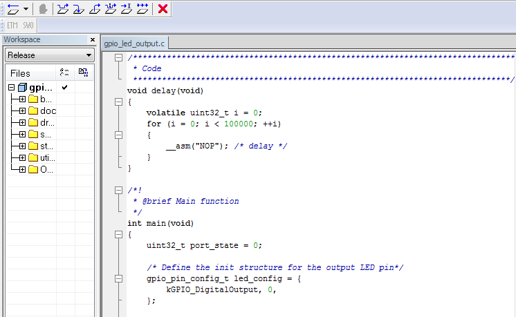
Build an Example Application
The following steps will guide you through opening the led_output application. These steps may change slightly for other example applications as some of these applications may have additional layers of folders in their path.
-
If not already done, open the desired example application workspace. Most example application workspace files can be located using the following path:
<install_dir>/boards/<sdk_board_name>/<example_type>/<application_name>/iar</application_name></example_type></sdk_board_name></install_dir>Using the hello_world demo as an example, the path is:
/boards/lpcxpresso54608/driver_examples/gpio/led_output/iar -
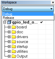
Select the desired build target from the drop-down. For this example, select the “hello_world – Debug” target
-
To build the application, click the “Make” button, highlighted in red below
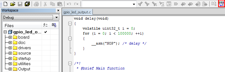
-
The build will complete without errors:
Run an Example Application
The LPCXpresso54608 board comes loaded with the CMSIS-DAP debug interface from the factory. Connect the development platform to your PC via USB cable to J8 “Debug Link”
-
Click the "Download and Debug" button to download the application to the target

-
The application is then downloaded to the target and automatically runs to the main() function
-
Run the code by clicking the "Go" button to start the application

3.4 Running a Demo Using Keil
Build an Example Application
The following steps will guide you through opening the led_output application. These steps may change slightly for other example applications as some of these applications may have additional layers of folders in their path.
-
If not already done, open the desired example application workspace. Most example application workspace files can be located using the following path:
<install_dir>/boards/<sdk_board_name>/<example_type>/<application_name>/iar</application_name></example_type></sdk_board_name></install_dir>Using the hello_world demo as an example, the path is:
/boards/lpcxpresso54608/driver_examples/gpio/led_output/iar -
Select the desired build target from the drop-down. For this example, select the “hello_world – Debug” target
-
To build the application, click the “Make” button, highlighted in red below:
-
The build will complete without errors:
Run an Example Application
The LPCXpresso54608 board comes loaded with the CMSIS-DAP debug interface from the factory. Connect the development platform to your PC via USB cable to J8 “Debug Link”
-
Click the "Download and Debug" button to download the application to the target
-
The application is then downloaded to the target and automatically runs to the main() function
-
Run the code by clicking the "Go" button to start the application
Tera Term Tutorial
Tera Term Tutorial
Tera Term Tutorial
Tera Term is a very popular open source terminal emulation application. This program can be used to display information sent from your NXP development platform's virtual serial port.
- Download Tera Term from SourceForge. After the download, run the installer and then return to this webpage to continue
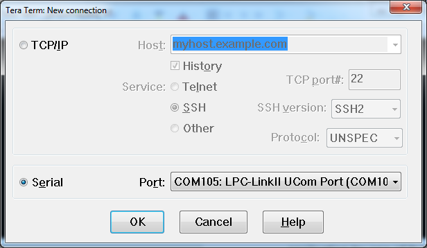
- Launch Tera Term. The first time it launches, it will show you the following dialog. Select the serial option. Assuming your board is plugged in, there should be a COM port automatically populated in the list
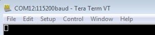
- Configure the serial port settings (using the COM port number identified earlier) to 115200 baud rate, 8 data bits, no parity and 1 stop bit. To do this, go to Setup → Serial Port and change the settings
- Verify that the connection is open. If connected, Tera Term will show something like below in it's title bar
- You're ready to go
PuTTY-Tutorial
PuTTY-Tutorial
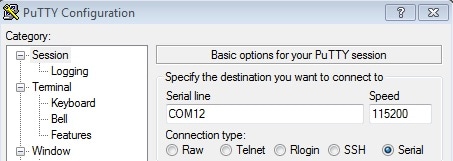
PuTTY Tutorial
PuTTY is a popular terminal emulation application. This program can be used to display information sent from your NXP development platform's virtual serial port.
- Download PuTTY using the button below. After the download, run the installer and then return to this webpage to continue
- Launch PuTTY by either double clicking on the *.exe file you downloaded or from the Start menu, depending on the type of download you selected
- Configure In the window that launches, select the Serial radio button and enter the COM port number that you determined earlier. Also enter the baud rate, in this case 115200
- Click Open to open the serial connection. Assuming the board is connected and you entered the correct COM port, the terminal window will open. If the configuration is not correct, PuTTY will alert you
- You're ready to go
Support
Forums
Connect with other engineers and get expert advice on designing with the OM13094 evaluation board using our community sites.
On this page
- 2.1
Choose a Development Path:
- 2.2
Getting Started with the MCUXpresso SDK
- 2.3
Install your Toolchain
- 2.4
MCUXpresso Config Tools
- 2.5
Serial Terminal