- Analog Toolbox
- Getting Started with the PCA9958HN-ARD Evaluation Board
Getting Started with the PCA9958HN-ARD Evaluation Board
Contents of this document
-
Out of the Box
-
Plug It In
-
Configure Hardware
Sign in to save your progress. Don't have an account? Create one.
Purchase your PCA9958HN-ARD
1. Out of the Box
The NXP analog product development boards provide an easy-to-use platform for evaluating NXP products. The boards support a range of analog, mixed-signal and power solutions. They incorporate monolithic integrated circuits and system-in-package devices that use proven high-volume technology. NXP products offer longer battery life, a smaller form factor, reduced component counts, lower cost and improved performance in powering state-of-the-art systems.
This page will guide you through the process of setting up and using the PCA9958HN-ARD evaluation board.
1.1 Kit Contents and Packing List
The kit contents include:
- Assembled and tested evaluation board in an anti-static bag
- Quick start guide
2. Plug It In
2.1 Board Features
- A complete evaluation platform for the PCA9958HN 24-channel SPI-bus 63 mA/5.5 V constant current LED driver
- Easy to use GUI based software demonstrates the capabilities of the PCA9958HN.
- On-board white and RGB LEDs for variable experiments
- Convenient test points for easy scope measurements and signal access
- USB interface to the host PC
- Power supply from USB port (x2) or external power supply can be used to power PCA9958HN evaluation board
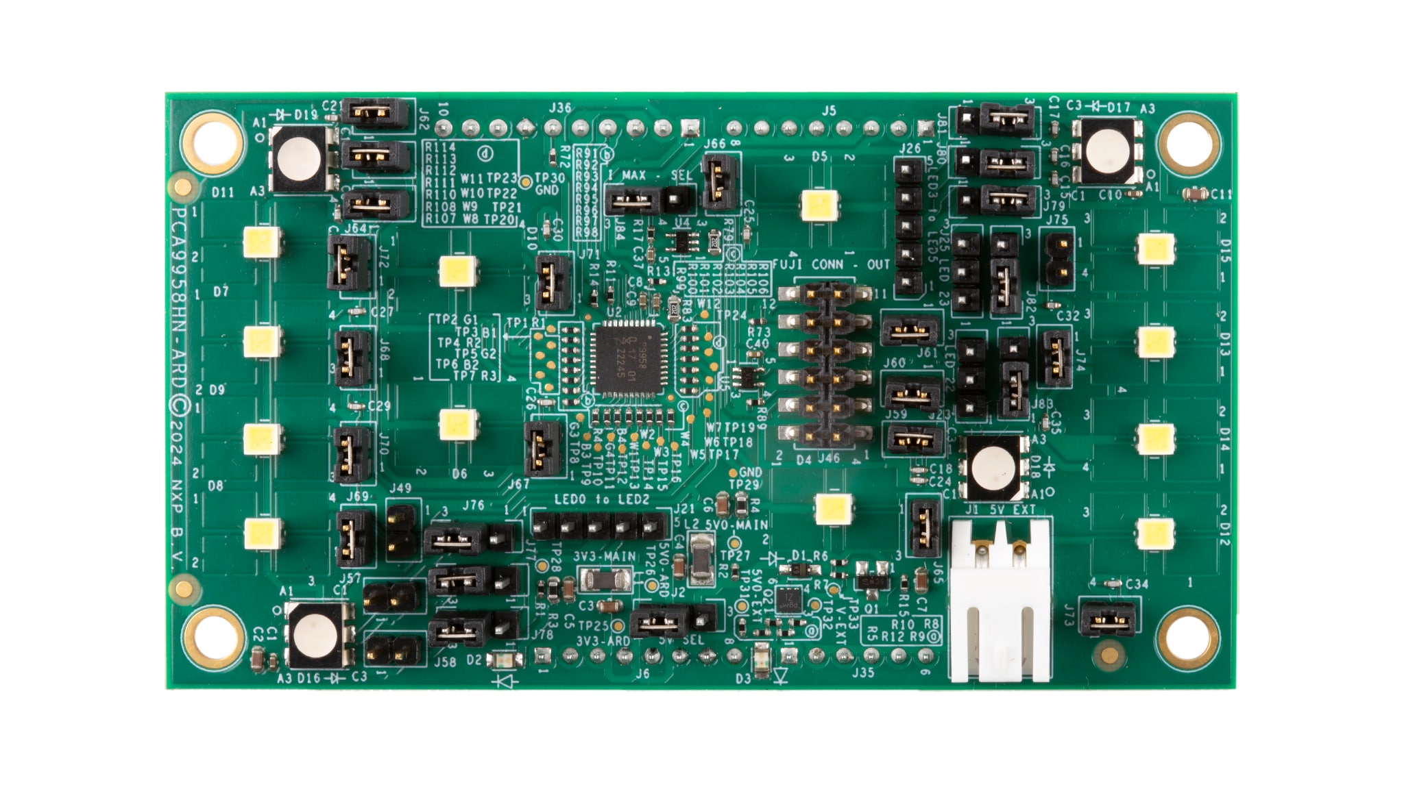
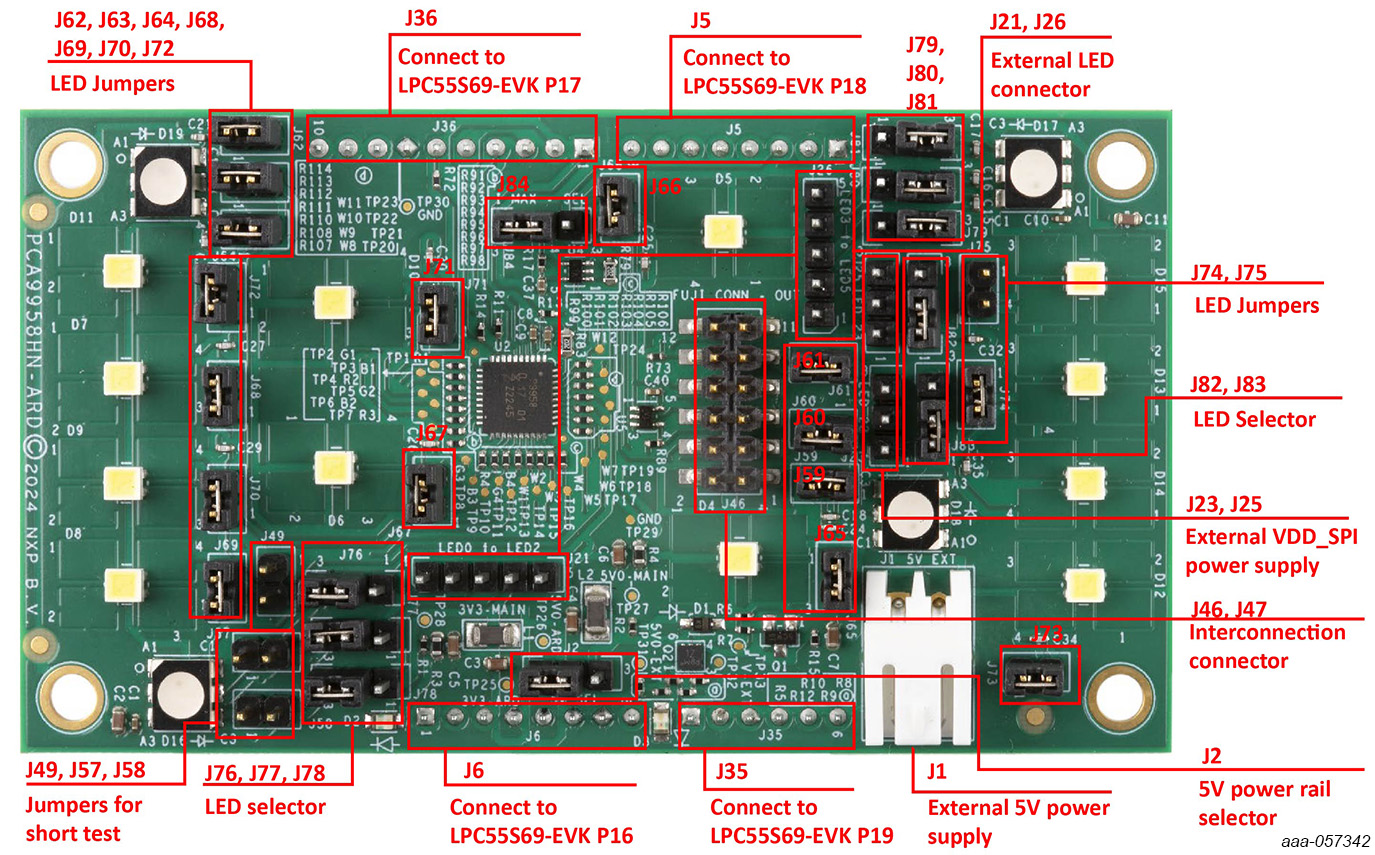
2.2 Board Description
J5/J6/J35/J36are connected to the LPC55S69-EVKMCU board for PCA9958HN-ARD power supply and SPI bus interface.J1selects external 5 V power supply.- 2 selects 5 V power rail.
J23,J25selects external VDD_SPI power supply.
| Device | Description | Location |
|---|---|---|
| PCA9958HN | 24-channel SPI serial bus 63 mA/5.5 V constant current LED driver | U2 |
| 74LVC1G66GW | Bilateral switch | U4, U5 |
| BC807-40 | 45 V. 500 mA PNP general-purpose transistor | Q1 |
| PMDPB80XP | 20 V. dual P-channel Trench MOSFET | Q2 |
| Red LED | 3.3 V power supply LED | D2 |
| Red LED | 5 V power supply LED | D3 |
| White LED | User white LED | D4, D5, D6, D7, D8, D9, D10, D11, D12, D13, D14, D15 |
| RGB LED | User RGB LED | D16, D17, D18, D19 |
| Inductors | 100 Ohms | L1, L2 |
| Jumper | Default Setting | Comment |
|---|---|---|
J5, J6, J35, J36 |
Arduino connector | |
J1 |
External 5 V power supply pins | |
J2 |
1-2 | 5 V power rail selector |
J21, J26 |
External LED connector for D16, D17 | |
J23, J25 |
External VDD_SPI power supply pins | |
J46, J47 |
Interconnection connector | |
J49, J57, J58 |
Open | Jumpers for short test |
J59, J60, J61, J62,
              J63, J64, J65, J66,
              J67, J68, J69, J70,
              J71, J72, J73, J74,
J75 |
1-2 | Jumpers for on-board LEDs connection |
J76, J77, J78, J79,
              J80, J81, J82, J83,
J84 |
2-3 | On-board / external LED selector |
Configure Hardware
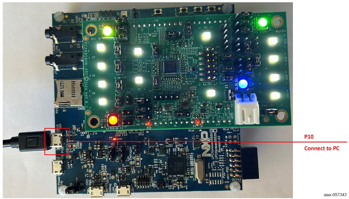
3.1 Configure Hardware
PCA9958HN-ARD evaluation board is connected to the LPC55S69-EVK MCU board using four connectors
(J5/J6/J35/J36 on PCA9958HN-ARD board and P16/P17/P19/P18 on LPC55S69-EVKboard) for SPI-bus and
power supply.
The LPC55S69-EVKMCU board communicates with PCA9958HN demo GUI through PC USB port and uses SPI to communicate to PCA9958HN.
Design Resources
Board Information
Additional References
In adition to our PCA9958HN-ARD board page, you may also visit:
Product pages: PCA9958 24-Bit 63 mA Current LED Driver with SPI
LPCXpresso55S69 Development Board: LPCXpresso55S69 Development Board