- Analog Toolbox
- Getting Started with the PCF85053ATK-ARD Evaluation Board
Getting Started with the PCF85053ATK-ARD Evaluation Board
Contents of this document
-
Out of the Box
-
Get Hardware
-
Installing and Configuring Software Tools
-
Configure the Hardware
Sign in to save your progress. Don't have an account? Create one.
Purchase your PCF85053ATK-ARD – PCF85053ATK Evaluation Board
1. Out of the Box
The NXP analog product development boards provide an easy-to-use platform for evaluating NXP products. The boards support a range of analog, mixed-signal and power solutions. They incorporate monolithic integrated circuits and system-in-package devices that use proven high-volume technology. NXP products offer longer battery life, a smaller form factor, reduced component counts, lower cost and improved performance in powering state-of-the-art systems. This page will guide you through the process of setting up and using the PCF85053ATK- ARD board.
1.1 Kit Contents and Packing List
The PCF85053ATK-ARD kit contents include:
- Assembled and tested evaluation board in an antistatic bag
1.2 Assumptions
Familiarity with the I²C-bus is helpful but not required.
1.3 Static Handling Requirements
This device is sensitive to ElectroStatic Discharge (ESD). Therefore care should be taken during transport and handling. Use a ground strap or touch the PC case or other grounded source before unpacking or handling the hardware.
1.4 Minimum System Requirements
- Computer with Windows 10
- One USB port (either 3.0 or 2.0 or 1.1 compatible)
- One of three EVK boards (MIMXRT1050-EVK, LPC55S69-EVK, MIMXRT685-EVK) along with the associated firmware / GUI software
- USB cable for power and data connection between PC and EVK board (if not included in the EVK package)
2. Get Hardware
2.1 Board Features
- Equipped with Arduino Uno R3 compatible headers for direct connection to Arduino compatible MCU EVKs
- On-board connector for external access and monitoring for I²C-bus / Alert / CLKOUT
- 1.8 V / 3.3 V selectable power supply
- On-board backup battery cell
- Fully with MIMXRT1050-EVK board, including GUI (Windows 10)
- Fully compatible with LPCXpresso55S69 dev. board, including GUI (Windows 10)
- Fully compatible with MIMXRT685-EVK board, including GUI (Windows 10)
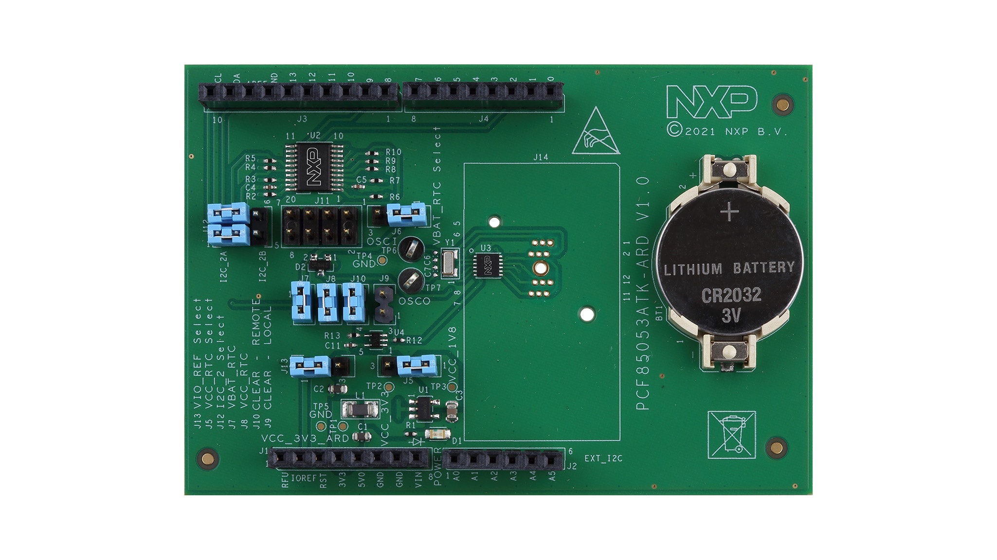
2.2 Board Description
The PCF85053ATK-ARD evaluation board is an expansion board equipped with Arduino headers, designated for easy test and design of PCF85053ATK IC, real-time clock/calendar with alarm function, battery switchover and timestamp functionality, controlled through two fast-mode I²C-buses.
The board is fully compatible with MIMXRT1050-EVKB, LPCXpresso55S69 and MIMXRT685-EVK, including GUI software control. The board can be attached to any device equipped with Arduino headers.
3. Installing and Configuring Software Tools
3.1 Installing and Configuring Software Tools
PCF85053ATK-ARD evaluation board is designed and built as an expansion board able to work in conjunction with a motherboard equipped with an Arduino header. The board was built to be fully compatible with the following NXP Evaluation (EVK) boards:
- MIMXRT1050-EVK Board
- LPCXpresso55S69 Development Board
- i.MX 8M Mini LPDDR4 EVK Board
Each above mentioned evaluation / development board has firmware support which can be downloaded from NXP company site. Before starting, the EVK motherboard must be programmed with the corresponding firmware package.
Additionally, a GUI application (Windows 10) is available for download from the NXP site, allowing rapid testing and operation of PCF85053ATK-ARD expansion board through one of the above mentioned EVK. The GUI application is common for all three EVKs. For details regarding installation of the EVK firmware and GUI host software on PC, please download UM11581 - Arduino Shields GUI and firmware installation .
Once the software is installed, the first step is to select the correct combination EVK – PCF85053ATK-ARD expansion board and then the board can be controlled from the GUI interface.
4. Configure the Hardware
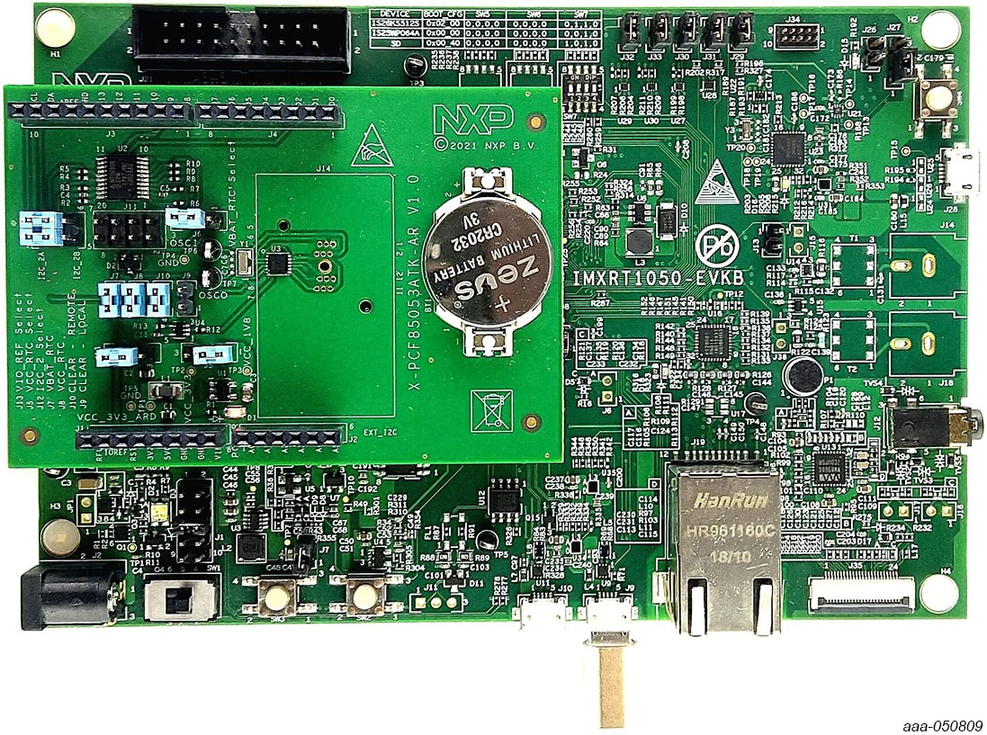
4.1 Using the PCF85053ATK-ARD with an MIMXRT1050-EVK Board
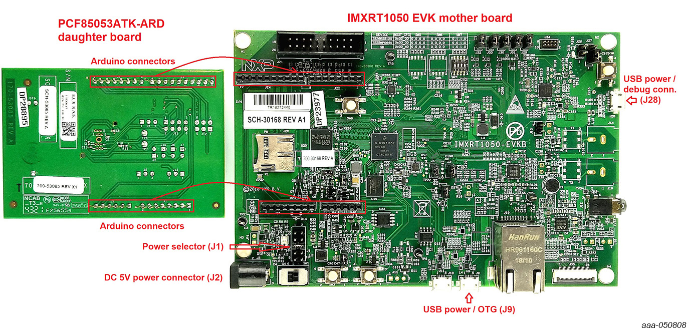
Figure 3 shows the required hardware for operation of the PCF85053ATK-ARD expansion board with MIMXRT1050-EVK. The following items are necessary:
- One MIMXRT1050-EVK board
- One PCF85053ATK-ARD expansion board
- One USB-A / USB Micro-B cable
- A PC with Windows 10 operating system
The MIMXRT1050-EVK motherboard can be powered by one of the three methods:
- Connecting an external 5VDC power supply to the barrel power connector (
J2) on the board - Connecting an USB cable from the PC to the Micro-B USB connector (
J9) on the board - Connecting an USB cable from the PC to the USB connector (
J28) on the board
When the PC is connected through the USB connectors J9 and J38, the EVK can be powered and at the same time linked to the PC for data exchange.
The older USB ports (from PC) are not able to deliver the necessary current (500mA), before establishing the communication, use an external power supply (connected to J2).
From J1 on the EVK board (see Figure 3) the user can select the power configuration for the motherboard. For further details, refer to the MIMXRT1050 EVKB Board Hardware User’s Guide.
To configure the hardware and workstation, complete the following procedure:
- Configure the suitable power configuration of EVK (
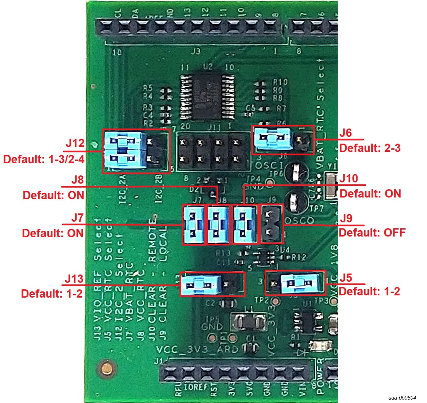
J1). If usingJ28for power supply, theJ1jumper shall be placed in position 5-6. If using an external power supply (connected toJ2), the jumperJ1will be placed in position 1-2 - Place jumpers on
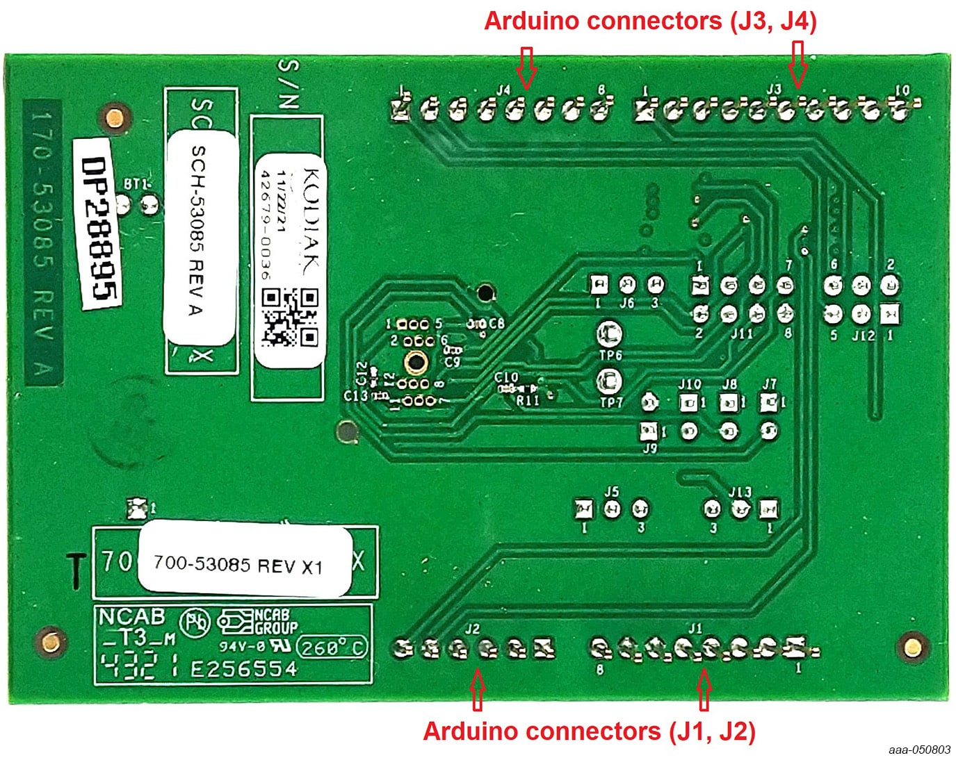
J12in 1-2/3-4 position (default) - Insert the PCF85053ATK-ARD expansion board on the Arduino connector of the EVK (see Figure 3 and Figure 4)
- Using USB connector
J9, connect the EVK board to an USB port of the computer - Install the MIMXRT1050 target firmware (download from NXP site and see UM11581, Arduino shields GUI and firmware installation manual for step-by-step instructions)
- Install GUI application (see UM11581, Arduino shields GUI and firmware installation manual)
- Open the GUI application to operate the device from the PC
Figure 4 shows the boards during the operation.
4.2 Using the PCF85053ATK-ARD with an LPCXpresso55S69 Development Board
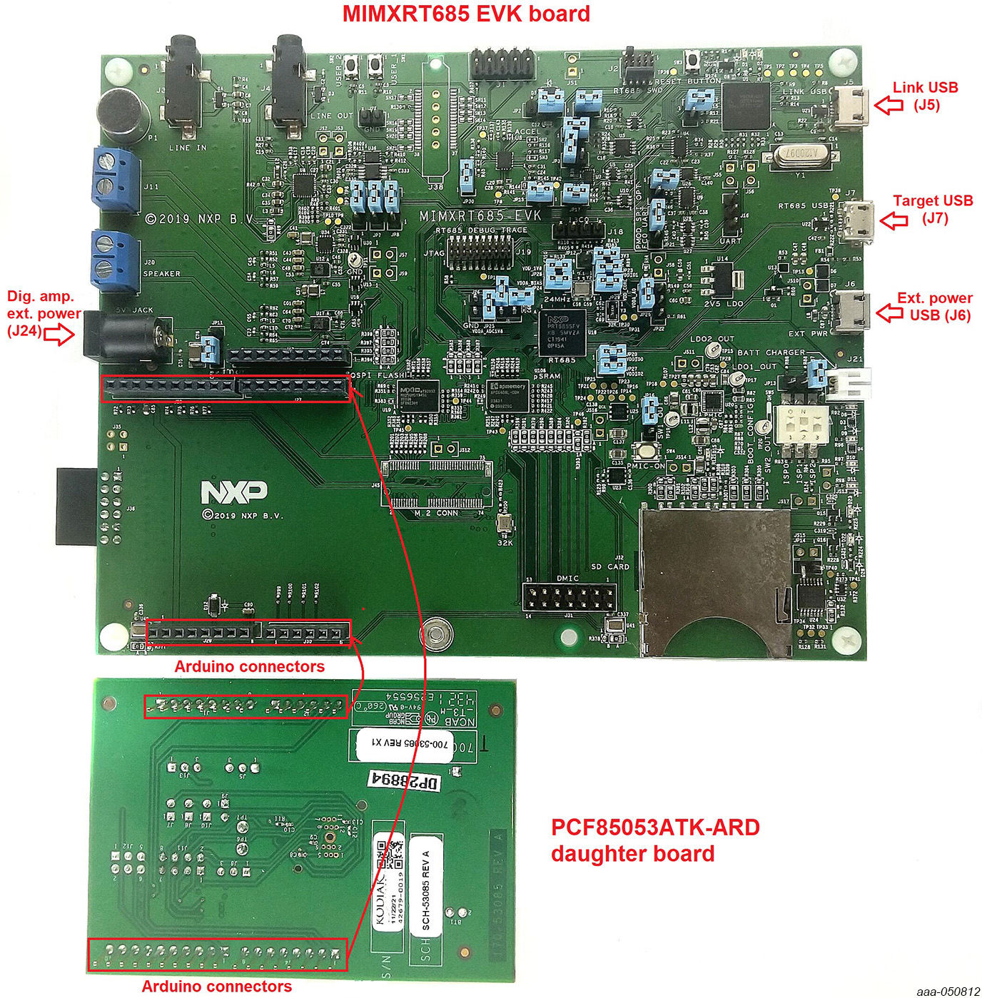
The third EVK board which can be used with the PCF85053ATK-ARD board, is MIMXRT685-EVK. Figure 7 shows the two boards, before assembly and operation. The following items are necessary to test and operate the board assembly:
- One MIMXRT685-EVK board
- One PCF85053ATK-ARD expansion board
- One USB-A / USB Micro-B cable
- Two jumper wires
- A PC with Windows 10 operating system
There are three ways to power-up the MIMXRT685-EVK board: through Link USB (J5), External Power USB (J6) and Target USB (J7). The Barrel connector J24 is designed to supply the digital amplifier section, therefore cannot be used to supply the MIMXRT685-EVK board. The datalink between the PC workstation and the EVK is realized through the Target USB (J7). Using the connector J7 and a USB-cable, the assembly MIMXRT685-EVK / PCF85053ATK-ARD can be simultaneously powered and connected to the PC, to be operated from the GUI application.
The user may find details regarding power-up and operation of the setup assembly in MIMXRT685-EVK UM11159 user manual. The pdf file can be downloaded from NXP company site.
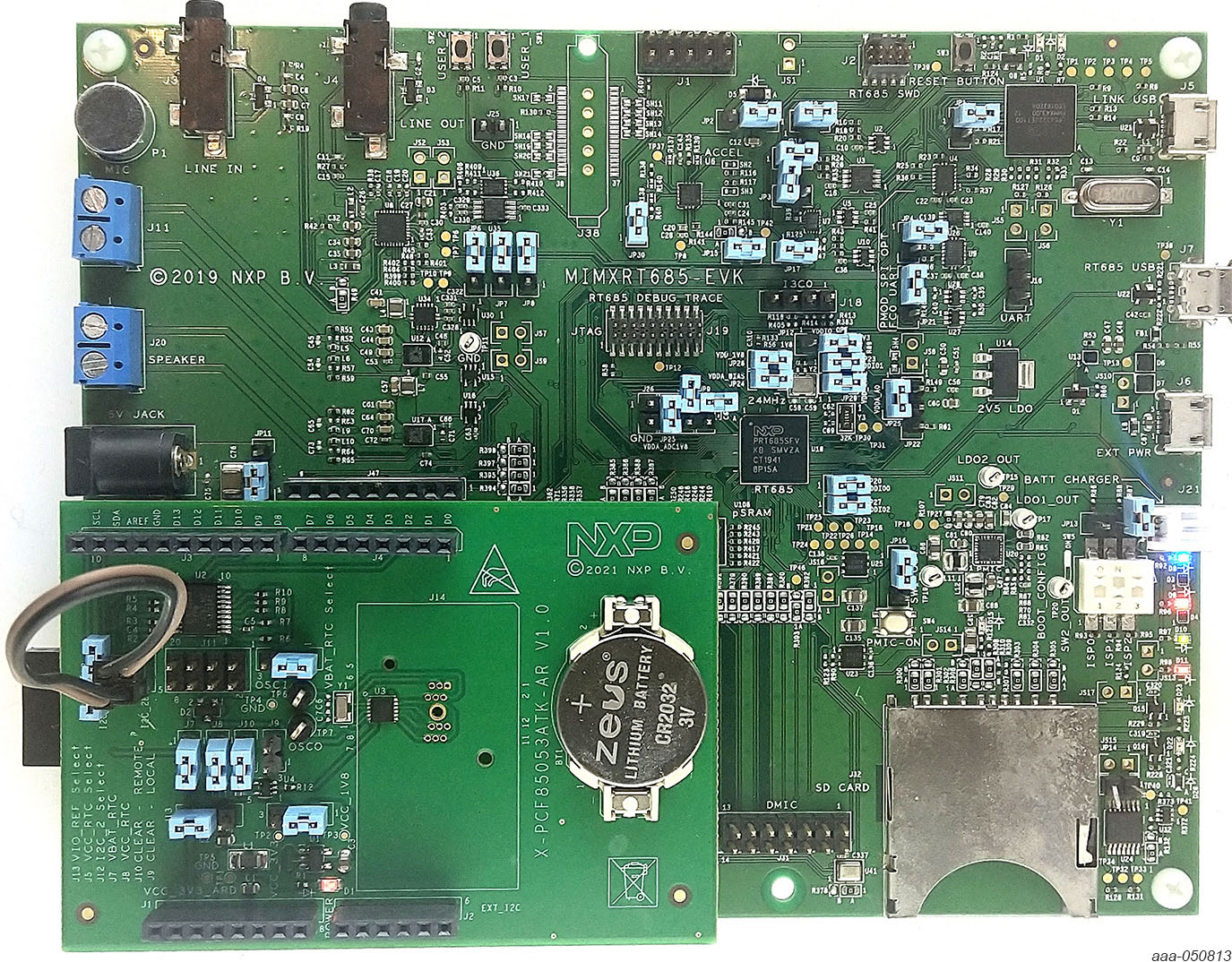
To configure and operate the setup, follow the below steps:
- Insert the PCF85053ATK-ARD onto the MIMXRT685-EVK board
- Configure
J12jumper header as follows: connect pin 3 to pin 6 and pin 4 to pin 5 using the two jumper wires (see Figure 8) - Power-up the EVK board using a USB Type C cable attached to PORT 2
- Connect the EVK to the PC, using a USB Micro-B cable, attached to
J7target USB connector - Install the MIMXRT1050 target firmware (download UM11581, Arduino shields GUI and firmware installation manual from NXP site)
- Install GUI application on the PC (see the instruction file referred in the above step)
- Open the GUI application to operate the device from the PC
4.3 Using the PCF85053ATK-ARD with an MIMXRT685-EVK Board
The third EVK board which can be used with the PCF85053ATK-ARD board, is MIMXRT685-EVK. Figure 7 shows the two boards, before assembly and operation. The following items are necessary to test and operate the board assembly:
- One MIMXRT685-EVK board
- One PCF85053ATK-ARD expansion board
- One USB-A / USB Micro-B cable
- Two jumper wires
- A PC with Windows 10 operating system
There are three ways to power-up the MIMXRT685-EVK board: through Link USB (J5), External Power USB (J6) and Target USB (J7). The Barrel connector J24 is designed to supply the digital amplifier section, therefore cannot be used to supply the MIMXRT685-EVK board. The datalink between the PC workstation and the EVK is realized through the Target USB (J7). Using the connector J7 and a USB-cable, the assembly MIMXRT685-EVK / PCF85053ATK-ARD can be simultaneously powered and connected to the PC, to be operated from the GUI application.
The user may find details regarding power-up and operation of the setup assembly in MIMXRT685-EVK UM11159 user manual. The pdf file can be downloaded from NXP company site.
To configure and operate the setup, follow the below steps:
- Insert the PCF85053ATK-ARD onto the MIMXRT685-EVK board
- Configure
J12jumper header as follows: connect pin 3 to pin 6 and pin 4 to pin 5 using the two jumper wires (see Figure 8) - Power-up the EVK board using a USB Type C cable attached to PORT 2
- Connect the EVK to the PC, using a USB Micro-B cable, attached to
J7target USB connector - Install the MIMXRT1050 target firmware (download UM11581, Arduino shields GUI and firmware installation manual from NXP site)
- Install GUI application on the PC (see the instruction file referred in the above step)
- Open the GUI application to operate the device from the PC
4.4 Using PCF85053ATK-ARD with Another Device
The PCF85053ATK-ARD expansion board can be operated with any other EVK boards which has an Arduino header. There are two options to connect the board: using other EVK equipped with an Arduino header, and an EVK without Arduino header. In the first case, a firmware shall be developed according to PCF85053A specifications, and then simply attach PCF85053ATK-ARD expansion board to the EVK to operate the board. In the second case, using the pin chart of Arduino connectors, make the necessary electrical connections (for power, I²C-bus and control lines) and develop the desired firmware, assuring that it is compliant with the IC specifications. Use PCF85053A data sheet to read details about internal registers of the DUT IC and data exchange between internal controller and the EVK. Assure correct electrical connections and avoid data conflicts on the signal lines to prevent IC damage.
Design Resources
Board Information
Additional References
In addition to our PCF85053A, Bootable CPU RTC with Two I²C Buses, 128 Byte SRAM and Alarm Function page, you may also want to visit:
On this page
- 1.1
Kit Contents and Packing List
- 1.2
Assumptions
- 1.3
Static Handling Requirements
- 1.4
Minimum System Requirements