Getting Started with the i.MX93 EVK
Contents of this document
-
Out of the Box
-
Get Software
-
Build, Run
-
Developer Experience
Sign in to save your progress. Don't have an account? Create one.
Purchase your i.MX 93 Evaluation Kit
1. Out of the Box
The following section describes the steps to boot the i.MX 93 EVK.
Development kit contains:
- i.MX 93 EVK board along with M.2 module with NXP’s Wi-Fi 6 Tri-radio IW612
- Power Supply: USB Type-C 45W power delivery supply, 5 V/3 A; 9 V/3 A; 15 V/3 A; 20 V/2.25 A supported
- Cable: Assembly, USB 2.0, Type-C male to Type-A male
- Software: Linux BSP image programmed in eMMC
- Quick start guide
Get started on developing your application on the i.MX 93 EVK by referring to the out-of-the-box video, available at i.MX 93 applications processor documentation.
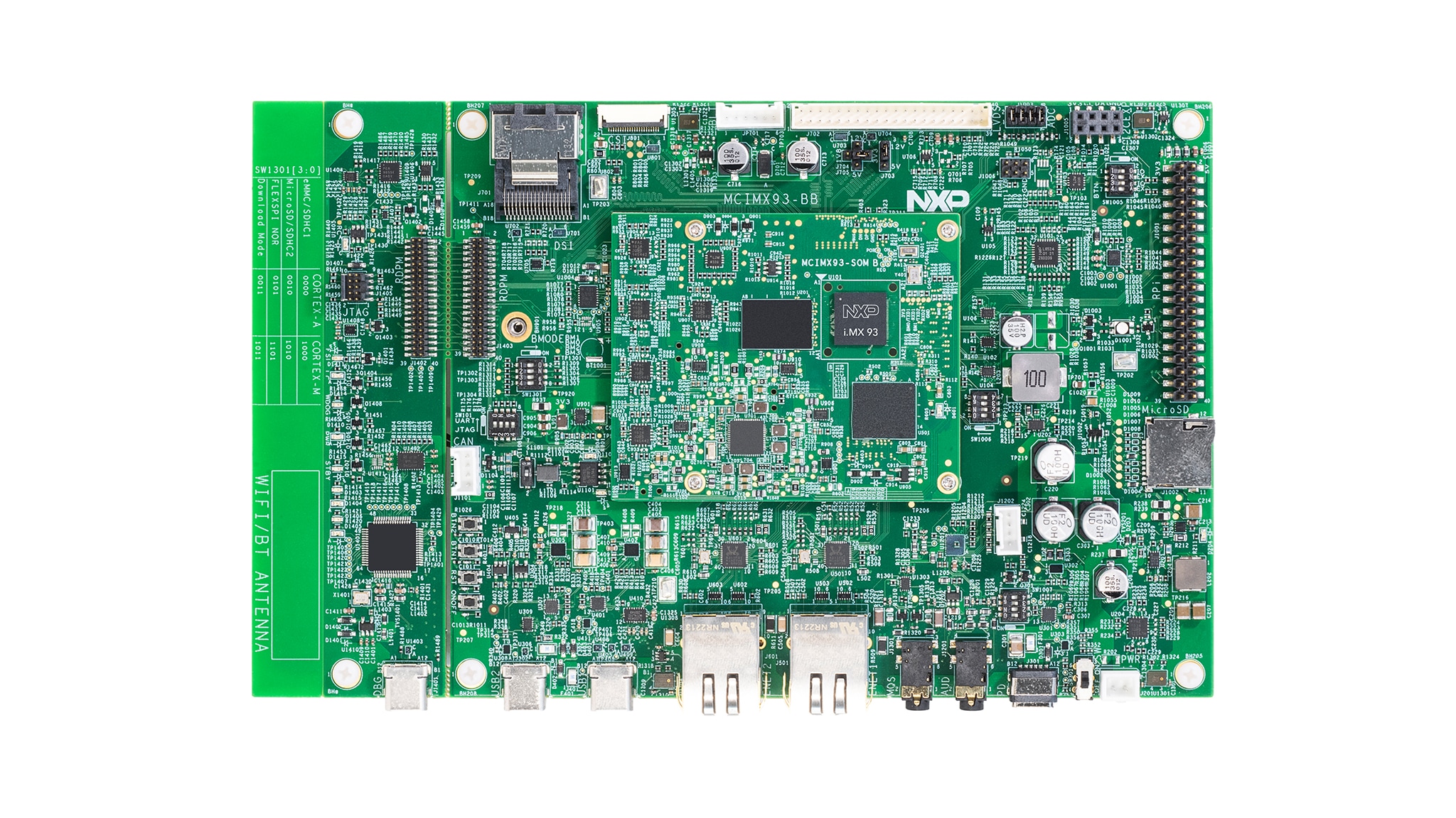
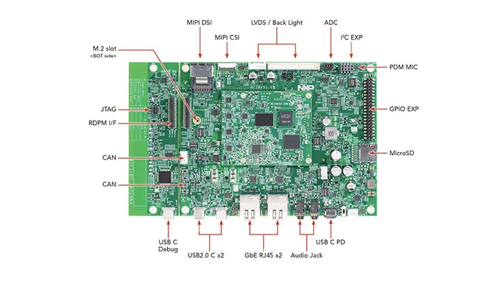
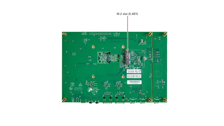
1.1 Get Familiar With the Board
1.2 Boot From eMMC
The i.MX 93 EVK comes with a pre-built NXP Linux binary demo image flashed on the eMMC. Without modifying the binary inside, booting from the eMMC provides a default system with certain features for building other applications on top of Linux.
To understand more about NXP's Embedded Linux®, MCUXpresso SDK, continue reading the next sections.
1.3 Connect USB Debug Cable
Connect the supplied USB Type-C cable to the debug UART port J1401, then connect the other end of the cable to a host computer.
Four UART connections will appear on the host computer. The third port is for A55 core and the fourth port is for M33 core system debugging.
If you are unfamiliar with terminal applications, please view one of the following tutorials before continuing to step 1.4: Minicom Tutorial, Tera Term Tutorial, PuTTY Tutorial.
1.4 Connect the HDMI Cable
To see the user interface provided with the image binary, connect a monitor via the MIPI-DSI J701 with IMX-MIPI-HDMI cable.
1.5 Boot Switch Setup
| BOOT MODE | BOOT CORE | SW1301-4 | SW1301-3 | SW1301-2 | SW1301-1 |
|---|---|---|---|---|---|
| From internal fuses | Cortex-A55 | 0 | 0 | 0 | 1 |
| Serial Downloader | Cortex-A55 | 0 | 0 | 1 | 1 |
| USDHC1 8-bit eMMC 5.1 | Cortex-A55 | 0 | 0 | 0 | 0 |
| USDHC2 4-bit SD3.0 | Cortex-A55 | 0 | 0 | 1 | 0 |
| FlexSPI Serial NOR | Cortex-A55 | 0 | 1 | 0 | 1 |
| FlexSPI Serial NAND 2K page | Cortex-A55 | 0 | 1 | 1 | 1 |
| Infinite Loop | Cortex-A55 | 0 | 1 | 0 | 0 |
| Test Mode | Cortex-A55 | 0 | 1 | 1 | 0 |
| From internal fuses | Cortex-M33 | 1 | 0 | 0 | 1 |
| Serial Downloader | Cortex-M33 | 1 | 0 | 1 | 1 |
| USDHC1 8-bit eMMC 5.1 | Cortex-M33 | 1 | 0 | 0 | 0 |
| USDHC2 4-bit SD3.0 | Cortex-M33 | 1 | 0 | 1 | 0 |
| FlexSPI Serial NOR | Cortex-M33 | 1 | 1 | 0 | 1 |
| FlexSPI Serial NAND 2K page | Cortex-M33 | 1 | 1 | 1 | 1 |
| Infinite Loop | Cortex-M33 | 1 | 1 | 0 | 0 |
| Test Mode | Cortex-M33 | 1 | 1 | 1 | 0 |
1.6 Connect Power Supply
Connect the power supply cable to the power connector (J301).
Power the board by flipping the switch (SW1301).
The processor starts executing from the on-chip ROM code. With the default boot switch setup, the code reads the fuses to define the media where it is expected to have a bootable image. After it finds a bootable image, the U-Boot execution should begin automatically.
Information is printed in the serial console for the Arm® Cortex®-A55. If you do not stop the U-Boot process, it continues to boot the kernel.
Congratulations, Linux Boot is complete.
As the board boots up, you will see 2 penguins appear in the upper left-hand corner of the monitor, and then you will see the Linux terminal Icon on the top left and timer on right top corner. Congratulations, you are up and running.
2. Get Software
This section is applicable ONLY if attempting to load a Linux® operating system on the board.
The i.MX Linux board support package (BSP) is a collection of binary files, source code and support files that are used to boot an Embedded Linux image on a specific i.MX development platform.
Current releases of Linux binary demo files can be found on the i.MX Linux download page. Additional documentation is available in the i.MX Linux documentation bundle under the Linux sections of the i.MX Software and Development Tools.
2.1 Overview
Before the Linux OS kernel can boot on an i.MX board, the Linux kernel is loaded to a boot device (SD card, eMMC and so on) and the boot switches are set to boot that device.
There are various ways to download the Linux BSP image for different boards and boot devices.
This Getting Started guide only outlines a few methods of flashing the Linux BSP image to an emmc flash.
2.2 Download an NXP Linux BSP Pre-Built Image
The latest pre-built images for the i.MX 93 EVK are available on the Linux download page under the most current version on Linux.
The pre-built NXP Linux binary demo image provides a typical system and basic set of features for using and evaluating the processor. Without modifying the system, the users can evaluate hardware interfaces, test SoC features and run user space applications.
When more flexibility is desired, an SD card can be loaded with individual components (boot loader, kernel, dtb file and rootfs file) one-by-one or the *wic image is loaded and the individual parts are overwritten with the specific components.
2.3 Burn NXP Linux BSP Image Using Universal Update Utility (UUU)
In addition to the connections from Out of the Box, connect the
USB1 to the host machine using
the proper USB cable.
Turn off the board. Refer to the Boot Switch Setup section and configure the board to boot on serial download protocol (SDP) mode.
Depending on the OS used in the host machine, the way to transfer the Linux BSP image onto an SD card can vary. Choose an option below for detailed instructions:
Linux®
Install UUU on Linux Distro
Download the latest stable files from UUU GitHub page. If further assistance for UUU is needed, please refer to this extensive tutorial.
uuulibusb1(via apt-get or any other package manager)
Burn the NXP Linux BSP Image to the Board
The latest pre-built images for the i.MX 93 EVK are available on the Linux download page under the most current version of Linux.
The pre-built NXP Linux binary demo image provides a typical system and basic set of features for using and evaluating the processor. Without modifying the system, the users can evaluate hardware interfaces, test SoC features and run user space applications.
When more flexibility is desired, an SD card can be loaded with individual components (boot loader, kernel, dtb file and rootfs file) one-by-one or the .wic image is loaded and the individual parts are overwritten with the specific components.
By default, this procedure flashes the image to the emmc flash. Check the UUU GitHub page for reference on how to flash the image to other devices.
Open a terminal application and change the directory to the location where uuu and the latest Linux distribution for i.MX 93 EVK are located. Add execution permission to the uuu file and execute it. uuu will wait for the USB device to connect
$ chmod a+x uuu
                $ sudo ./uuu -b sd_all imx-boot-imx93-11x11-lpddr4x-evk-sd.bin-flash_singleboot
                imx-image-full-imx93evk.wic
Confirm i.MX93 EVK boot mode is switched to serial download mode, and turn on the board,
uuu will
start to flash the
images to the eMMC.
When it finishes, turn off the board and consult. If further assistance with configuring the board to boot from emmc, please consult the Boot Switch Setup.
Windows
Install UUU on Linux Distro
Download the latest stable files from UUU GitHub page. If further assistance for UUU is needed, please refer to this extensive tutorial.
uuu.exe- Serial USB drivers (depending on your board and Windows installation - check Windows Device Manager)
Burn the NXP Linux BSP Image to the Board
By default, this procedure flashes the image to the emmc flash. Check the UUU GitHub page for reference on how to flash the image to other devices.
Open the command prompt application and navigate to the directory where the uuu.exe file and the Linux release for the i.MX 93 EVK are located.
uuu.exe -b sd_all imx-boot-imx93-11x11-lpddr4x-evk-sd.bin-flash_singleboot
                imx-image-full-imx93evk.wic
Confirm i.MX93 EVK boot mode is switched to serial download mode, and turn on the board,
uuu will
start to flash the
images to the eMMC.
When it finishes, turn off the board and consult. If further assistance with configuring the board to boot from emmc, please consult the Boot Switch Setup.
If further assistance for UUU is needed, please refer to this extensive tutorial.
3. Build, Run
In the section, a brief guide of how to build Yocto BSP image for i.MX93 EVK is introduced.
The MCUXpresso software development kit (MCUXpresso SDK) provides comprehensive software source code to be executed in the i.MX 93 M33 core. If you do not wish to enable the Arm® Cortex®-M33 on i.MX 93 at this moment you can skip sub-section 3.2 and 3.3.
3.1 i.MX93 EVK Yocto BSP
To build i.MX93 EVK image from source code, please first check i.MX Yocto Project User's Guide to get familiar with Yocto project and Yocto build. Then please follow below steps to build image for i.MX93 Auto EVK.
- Download i.MX SW 2025 Q1 BSP Release:
$ repo init -u https://github.com/nxp-imx/imx-manifest -b imx-linux-styhead -m imx-6.12.3-1.0.0.xml $ repo sync - Yocto Project Setup:
$ DISTRO=fsl-imx-xwayland MACHINE=imx93-11x11-lpddr4x-evk source imx-setup-release.sh -b build-xwayland - Build images:
$ bitbake imx-image-full - Flashing SD card image:
$ imx-image-full-imx93-11x11-lpddr4x.rootfs.wic.zst | sudo dd of=/dev/sdx bs=1M && sync $ uuu -b sd_all imx-image-full-imx93-11x11-lpddr4x.rootfs.wic.zst - Or using uuu to burn image into SD card:
$ uuu -b sd_all imx-image-full-imx93-11x11-lpddr4x.rootfs.wic.zst - Change boot switch
SW5[1:4]to "0100" to select SD card boot, insert the SD card and power up the i.MX 93 EVK.
3.2 MCUXpresso SDK Overview
The MCUXpresso SDK is designed for the development of embedded applications for Cortex®-M33 standalone or collaborative use with the A cores. Along with the peripheral drivers, the MCUXpresso SDK provides an extensive and rich set of example applications covering everything from basic peripheral use case examples to demo applications. The MCUXpresso SDK also contains RTOS kernels and device stack and various other middleware to support rapid development.
This guide shows how to run the m33_image.bin demo provided by the release. For detailed information on MCUXpresso SDK and how to build and deploy custom demos, please visit MCUXpresso SDK site.
3.3 Run Applications Using U-Boot
This section describes how to run applications using an SD card and pre-built U-Boot image for i.MX processor.
- Following the steps from section Get Software, prepare an SD card with a pre-built U-Boot + Linux image from the Linux BSP package for the i.MX 93 processor. If you have already loaded the SD card with a Linux image, you can skip this step
- Insert the SD card in the host computer (Linux or Windows) and copy the application image (for example
m33_image.bin) to the FAT partition of the SD card - Safely remove the SD card from the PC
- Insert the SD card to the target board. Make sure to use the default boot SD slot and double check the Boot Switch Setup guide
- Connect the DEBUG UART connector on the board to the PC through a USB cable. The Windows OS installs the USB driver automatically, and the Ubuntu OS will find the serial devices as well. See Connect USB Debug Cable section for more instructions on serial communication applications. Open a second terminal on the i.MX93 EVK board's fourth enumerated serial port
- This is the Cortex-M33's serial console. Set the speed to 115200 bit/s, data bits 8, 1 stop bit (115200, 8N1), no parity Power up the board and stop the boot process by pressing any key before the U-Boot countdown reaches zero. At the U-Boot prompt on the first terminal, type the following commands
=> fatload mmc 1:1 0x80000000 m33_image.bin
=> cp.b 0x80000000 0x201e0000 0x10000
=> bootaux 0x1ffe0000 0
These commands copy the image file from the partition of the SD card into the Cortex-M33's TCM and releases the Cortex-M33 from reset.
4. Developer Experience
To enable faster development for users of all skill levels, NXP provides extensive example applications to showcase various features and capabilities of the platform.
4.1 Application Code Hub
The Application Code Hub (ACH) repository enables engineers to easily find microcontroller and processor software examples, code snippets, application software packs and demos developed by NXP in-house experts. This space provides a quick, easy and consistent way to find microcontroller and processor applications.
ACH provides filter and search options to quickly find specific applications. With the support of Git capabilities, there is an easy way to import and use applications within user’s development environments.
To learn more details of ACH, please visit this link.
4.2 GoPoint for i.MX Applications Processors
The GoPoint for i.MX Application Processors is a user-friendly application that launches pre-built applications packed with the Linux BSP, giving users an excellent out-of-the-box experience and hands-on experience with i.MX SoC's capabilities. GoPoint highlights advanced features while providing practical solutions for implementation, with source code and build recipes for the applications provided in GitHub.
To learn more details of GoPoint, please visit this link.
Minicom Tutorial
Serial Communication Console Setup
On the command prompt of the Linux host machine, run the following command to determine the port number:
$ ls /dev/ttyUSB*The smaller number is for Arm® Cortex®-A55 core and the bigger number is for Arm Cortex-M33 core.
Minicom
Use the following commands to install and run the serial communication program (minicom as an example):
- Install Minicom using Ubuntu package manager
- Launch Minicom using a console window using the port number determined earlier
- Configure Minicom as show in Figure
- The next step is to Connect the HDMI cable.
$ sudo apt-get install minicom$ sudo minicom /dev/ttyUSB* -s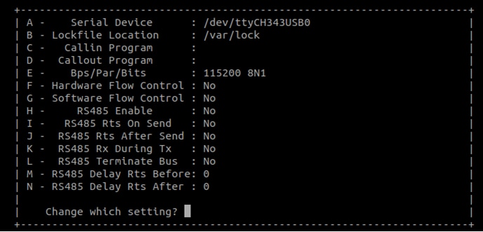
Tera Term Tutorial
Serial Communication Console Setup
The FTDI USB-serial chip on i.MX 93 enumerates 4 serial ports. Assume that the ports are COM11,COM12,COM13,COM14. The third Port(COM13) is for the serial console communication from Arm® Cortex®-A55 core and the fourth port(COM14) is for Arm Cortex-M33 core. The serial-to-USB drivers are available at FTD Chip Drivers.
Tera Term
Is an open source terminal emulation application. This program displays the information sent from the NXP development platform’s virtual serial port.
- Download Tera Term. After the download, run the installer and then return to this webpage to continue
- Launch TeraTerm. The first time it launches, it shows the following dialog. Select the serial option. Assuming your board is plugged in, there should be a COM port automatically populated in the list
- Configure the serial port settings (using the COM port number identified earlier) to 115200 baud rate, 8 data bits, no parity and 1 stop bit. To do this, go to Setup → Serial Port and change the settings
- Verify that the connection is open. If connected, Tera Term shows something like below in its title bar
- The next step is to Connect the HDMI cable
Putty Tutorial
Serial Communication Console Setup
TThe FTDI USB-serial chip on i.MX 93 enumerates 4 serial ports. Assume that the ports are COM11,COM12,COM13,COM14. The third Port(COM13) is for the serial console communication from Arm® Cortex®-A55 core and the fourth port(COM14) is for Arm Cortex-M33 core. The serial-to-USB drivers are available at FTD Chip Drivers
PuTTY is a popular terminal-emulation application. This program displays the information sent from the NXP development platform’s virtual serial port.
- Download PuTTY After the download, run the installer and then return to this webpage to continue.
- Launch PuTTY by either double clicking on the executable file you downloaded or from the Start menu, depending on the type of download you selected.
- Configure In the window that launches. Select the Serial radio button and enter the COM port number that you determined earlier. Also enter the baud rate, in this case 115200.
- Click Open to open the serial connection. Assuming the board is connected and you entered the correct COM port, the terminal window opens. If the configuration is not correct, PuTTY alerts you.
- The next step is to Connect the HDMI cable.