
S32K39/37/36 Microcontrollers for Electrification Applications
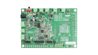
Devices in the FS27 automotive safety system basis chip (SBC) family are designed to support entry- and mid-range safety 28 nm microcontrollers. FS27 devices have multiple power supplies and the flexibility to work with other microcontrollers targeting automotive electrification. Possible FS27 applications include powertrain, chassis, safety and low-end gateway technology.
This family of devices consists of several versions that are pin-to-pin and software compatible. These versions support a wide range of applications with Automotive Safety Integrity Levels (ASIL) B or D, offering choices in the number of output rails, output voltage settings, operating frequencies, power up sequencing and integrated system-level features.
The FS27 features multiple switch mode regulators and low dropout (LDO) voltage regulators to supply the microcontroller, sensors, peripheral integrated circuits (ICs) and communication interfaces. It offers a high-precision reference voltage supply for the system, and for two independent tracking regulators. The FS27 also offers various functionalities for system control and diagnostics, including an analog multiplexer, general-purpose input/outputs (GPIOs), and selectable wake-up events from input/output (I/O), long-duration timer (LDT), serial peripheral interface (SPI) or Inter-Integrated Circuit (I²C) communications.
The FS27 is developed in compliance with the International Organization for Standardization (ISO) 26262 standard, and includes enhanced safety features with multiple fail-safe outputs. It uses the latest on-demand latent fault monitoring, and can be part of a safety-oriented system partitioning scheme covering both ASIL B and ASIL D safety integrity levels.
S32K39/37/36 Microcontrollers for Electrification Applications
Advanced High Voltage Isolated Gate Driver with Dynamic Gate Strength Control
Safety System Basis Chip with Low Power, for ASIL D Systems
Quick reference to our documentation types
2 documents
Compact List
1-5 of 6 hardware offerings
Quick reference to our software types.
1 software file
Note: For better experience, software downloads are recommended on desktop.