
KITVR5500AEEVM
Active
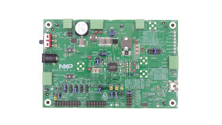
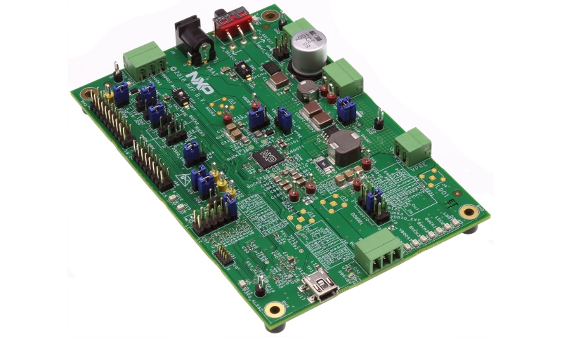
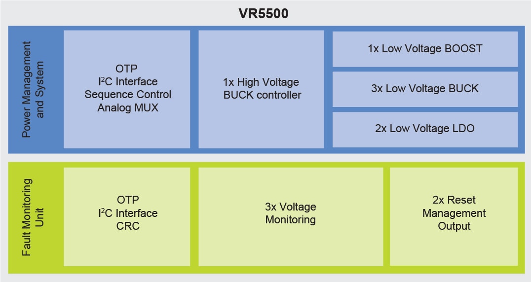
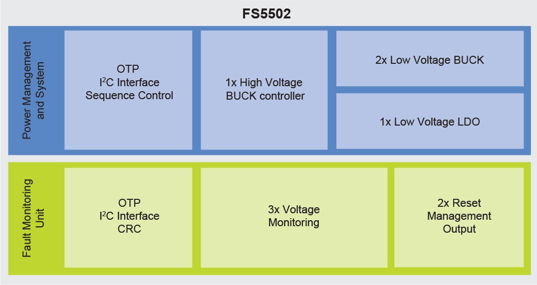
VR5500 / FS5502 PMIC Evaluation Board.
Kit Contains
- KITVR5500AEEVM board
- Power Supply mating connectors
- USB mini cable Type A Male / Type B Male
In Stock :21
Order from distributors