Getting Started with the KIT33772CTPLEVB Evaluation Board
Contents of this document
-
Out of the Box
-
Get Hardware
-
Configure the Hardware
Sign in to save your progress. Don't have an account? Create one.
Purchase your KIT33772CTPLEVB
1.Out of the Box
The NXP analog product development boards provide an easy-to-use platform for evaluating NXP products. The boards support a range of analog, mixed-signal and power solutions. They incorporate monolithic integrated circuits and system-in-package devices that use proven high-volume technology. NXP products offer longer battery life, a smaller form factor, reduced component counts, lower cost, and improved performance in powering state-of-the-art systems.
This page will guide you through the process of setting up and using the KIT33772CTPLEVB evaluation board.
1.1 Kit Contents and Packing List
The KIT33772CTPLEVB contents include:
- Assembled and tested KIT33772CTPLEVB in an antistatic bag
- One TPL cable
- Quick start guide
1.2 Additional Hardware
In addition to the kit contents, the following hardware is necessary or beneficial when working with this kit.
- A 3 to 6-cell battery pack, such as BATT-14AAAPACK, or a battery pack emulator, such as BATT-6EMULATOR
2. Get Hardware
2.1 Board Description
The KIT33772CTPLEVB serves as a hardware evaluation tool in support of NXP's MC33772C device. The MC33772C is a battery cell controller that monitors up to 6 lithium-ion battery cells. It is designed for use in both automotive and industrial applications. The device performs ADC conversion on the differential cell voltages and currents. It is also capable of battery charge coulomb counting and battery temperature measurements.
The KIT33772CTPLEVB is an ideal platform for rapid prototyping of MC33772C-based applications that involve current, voltage, and temperature sensing. The information is digitally transmitted to a microcontroller for processing. The evaluation board can be used in conjunction with a transceiver physical layer transformer driver (MC33664) to convert MCU SPI data bits to pulse bit information for the MC33772C and vice versa.
2.2 Board Features
- Daisy chain device connection
- LED indicator for operation mode
- Cell-balancing resistors
- Cell sense input with RC filter
- GPIO: digital I/O, wake-up inputs, convert trigger inputs, ratiometric analog inputs, analog inputs with absolute measurements
- EEPROM (connected to the IC with I2C interface) to store user-defined calibration parameters
- Current measurement input via external shunt
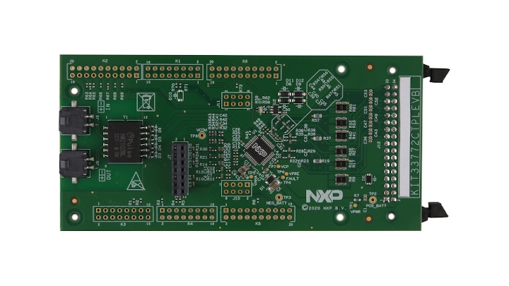
2.3 Board Components
Overview of the KIT33772CTPLEVB evaluation board
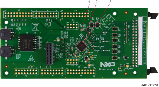
| Number | Label | Name | Description |
|---|---|---|---|
| 1 | D7 | VCOM LED | Indicates whether the device is in normal mode or in low-power mode |
| 2 | U2 | 24LC01BT-I/OT | IC memory EEPROM |
| 3 | U1 | MC33772C | Battery cell controller IC |
3. Configure the Hardware
3.1 Configure the Hardware
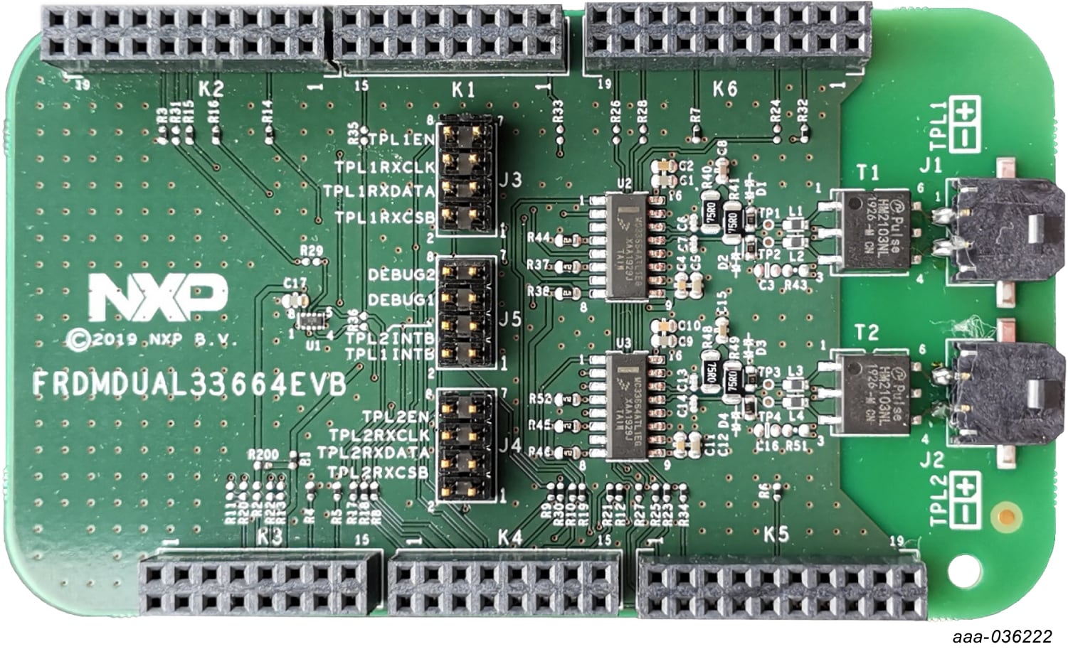
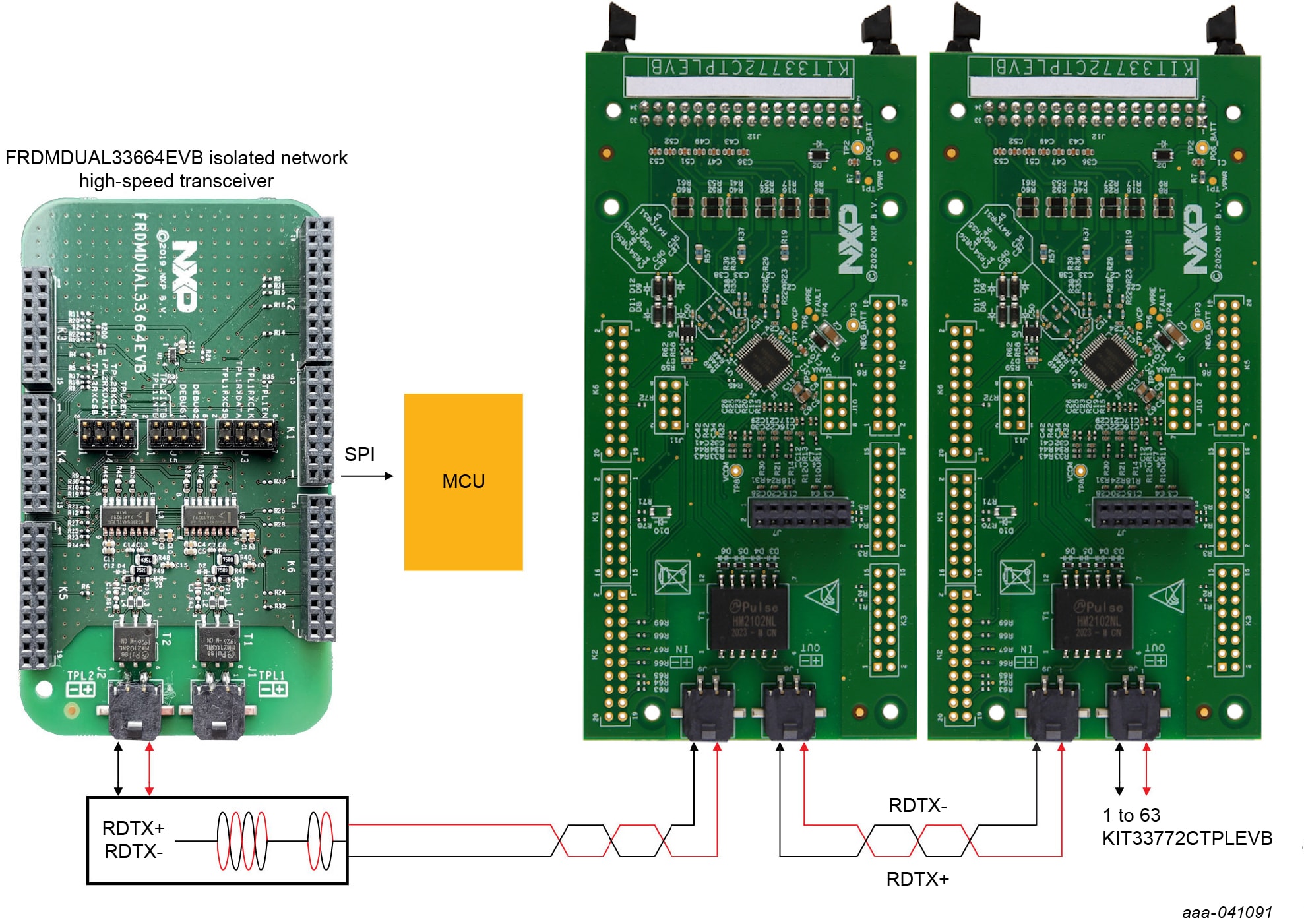
The KIT33772CTPLEVB kit is designed for use with the FRDMDUAL33664EVB in high-voltage isolated applications that provide a SPI-to-high-speed isolated communication interface. The FRDMDUAL33664EVB includes two MC33664 isolated network high speed transceivers allowing loopback connection. MCU SPI data bits are directly converted to pulse bit information.
3.2 Battery Stack Connection
The KIT33772CTPLEVB supports the use of a battery cell emulator such as the BATT-6EMULATOR board and BATT-14AAAPACK from NXP.
The BATT-6EMULATOR is a six-cell battery emulator board that provides an intuitive way to change the voltage across any of the six cells and four voltage outputs in order to emulate four external NTCs.
The emulator board can be connected to the KIT33772CTPLEVB J12 connector using the provided
supply cable.
To utilize the KIT33772CTPLEVB in combination with the BATT-6EMULATOR, a graphical user interface is available.
3.3 TPL Communication Connection
In a high-voltage Isolated application with a daisy chain configuration, up to 63 KIT33772CTPLEVB boards may be connected.
The TPL connections use the COMM connectors, J8 and J9.
Design Resources
Board Documents
Additional References
In addition to our MC33772C: 6-Channel Li-ion Battery Cell Controller IC page, you may also want to visit:
Tool Pages
Application Pages
Hardware Pages
Software Pages
Support
Forums
Connect with other engineers and get expert advice on designing with the KIT33772CTPLEVB on one of our community sites.