Getting Started with the TEA2016DB1519 Demo Board
Contents of this document
-
Get Started
-
Get Hardware
-
Get Software
-
Configure Hardware
Sign in to save your progress. Don't have an account? Create one.
Purchase your 240 W Demo Board
1. Get Started
The NXP analog product development boards provide an easy-to-use platform for evaluating NXP products. The boards support a range of analog, mixed-signal and power solutions. They incorporate monolithic integrated circuits and system-in-package devices that use proven high-volume technology. NXP products offer a smaller form factor, reduced component counts, lower cost and improved performance in powering state-of- the-art systems.
This page will guide you through the process of setting up and using the TEA2016DB1519 demo board.
1.1 Kit Contents
1.2 Required Equipment
- AC mains source
- Power analyzer (optional)
- Electronic load (minimum: 20 A at 12 V)
- Oscilloscope for observing operation behavior
- Windows PC with USB for parameter modifications via software and interface
- TEA2016DB1514v2 USB-I2C interface board (RDK01DB1563 kit, optional)
1.3 Windows PC Workstation
- PC with windows. Software tested for Windows 7 and Windows 10 but also works on XP, Vista and Windows 8
- 64 bit and 32 bit versions of Ringo software available for download
1.4 User Manuals
Refer to UM11234, UM11235, UM11527 and Ringo software package for additional details on the featured components and board configuration.
The Ringo software package contains documents, videos and tools.

2. Get Hardware
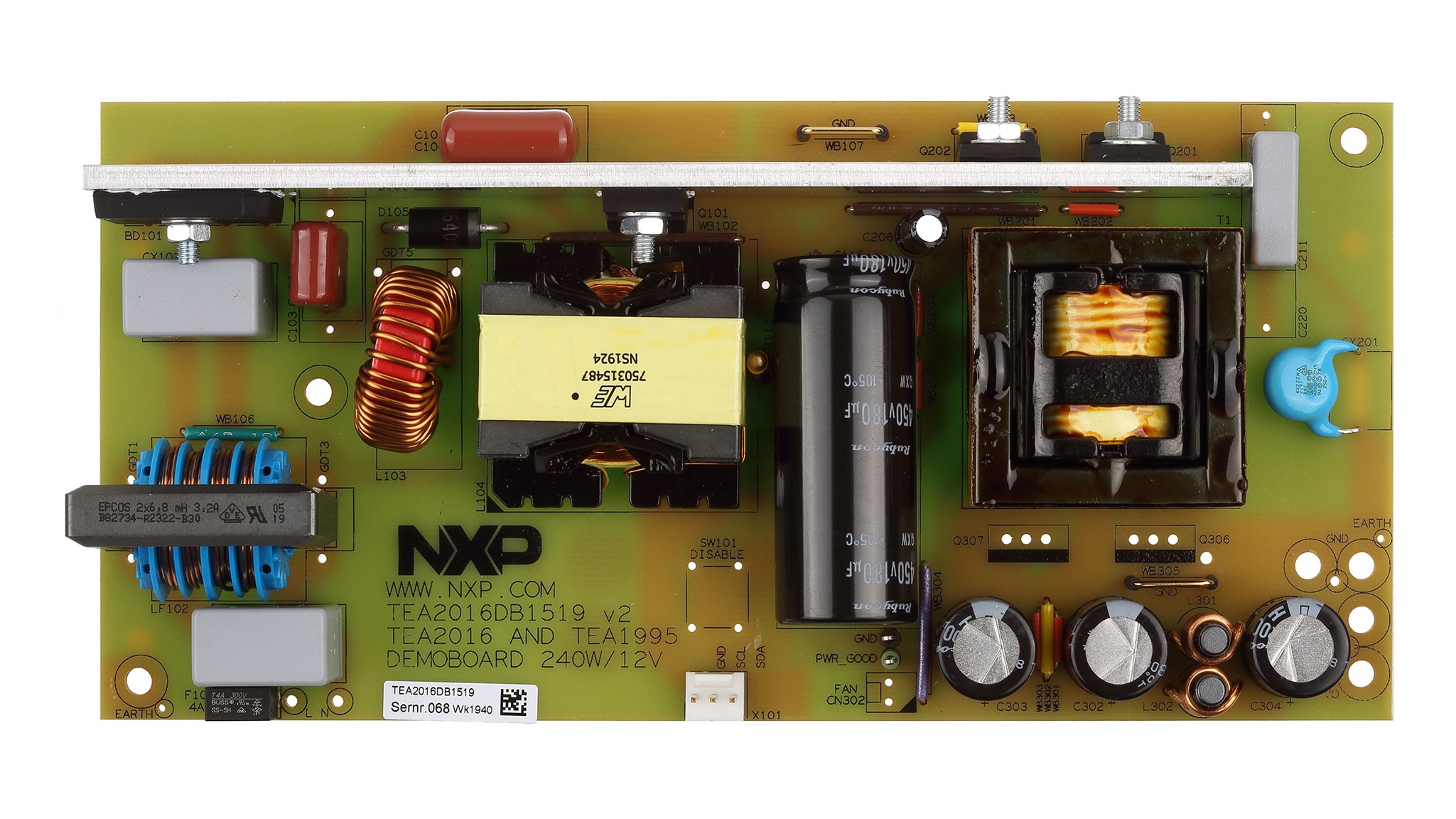
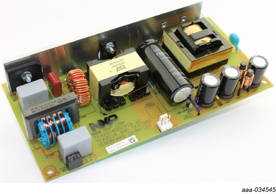
2.1 Board Description
TEA2016DB1519 240W 12 V 20 A power supply demo board
The demo board can operate at a mains input voltage between 90 V (RMS) and 264 V (RMS; universal mains). It contains three sub circuits:
- A BCM-type PFC converter
- A resonant LLC-type HBC converter
- An SR resonant LLC-type output stage
The purpose of the demo board is to show and evaluate the operation of the TEA2016 PFC + LLC controller and the Synchronous Rectifier TEA1995T in a single output voltage power supply, which includes the operation modes in a typical design. The performance passes general standards, including the EuP lot6 requirements.
| Symbol | Description | Value | Conditions |
|---|---|---|---|
| Input | |||
| Vi | input voltage | 90 V (RMS) to 264 V (RMS) | AC |
| fi | input frequency | 47 Hz to 63 Hz | |
| Pi (no load) | no-load input power | < 100 mW | at 230 V/50 Hz |
| Pi (load-250 mW) | standby power consumption | < 450 mW | at 230 V/50 Hz |
| Output | |||
| Vo | output voltage | 12 V | |
| Io | output current | 0 A to 20 A | continuous |
| Io(max) | maximum output power | 24 A | OPP level |
| Io(peak)max | maximum peak output current | 30 A | t < 50 ms; limited by power limit setting (155 %) |
| thold | hold time | > 10 ms | at 115 V/60 Hz |
| tstart | start time | < 0.5 s | at 115 V/60 Hz |
| η | efficiency | ≥ 89 % | average according to CoC |
2.2 Additional Board Support
In addition to the normal TEA2016 ICs, NXP Semiconductors provides special IC versions for product development. The difference is that the development IC samples include a second I2C interface for easy modification of settings while the IC is operating (“on the fly” changing). The TEA2016DB1519 demo board uses the development version of the TEA2016.
Refer to UM11234, UM11235, UM11527 and Ringo software package for additional details on the featured components and board configuration.
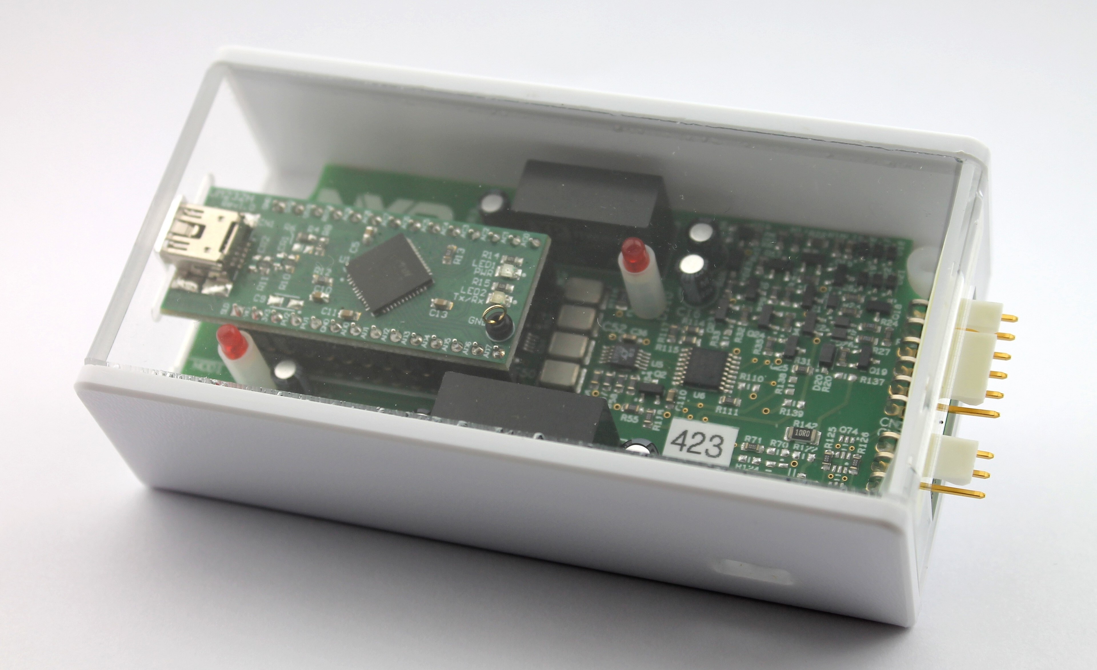
2.3 Interface Board
The TEA2016DB1514 interface board is a development tool that enables setting TEA2016 controller parameters from a computer. The available Ringo TEA2016 development software provides a graphical user interface (GUI) that can be installed on a computer.
The interface and software are intended for engineering work in a lab environment as part of power supply development. It is not suitable for consumer or industrial use.
2.4 IC Programming Board
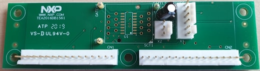
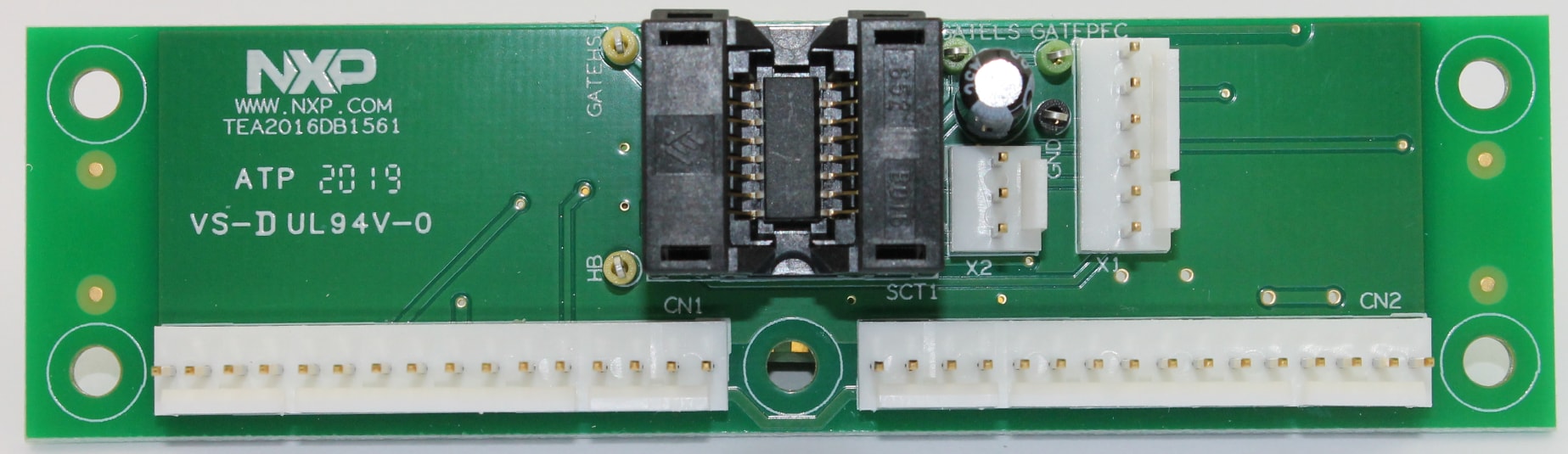
This board can be used to get familiar with programming TEA2016AATdev samples. A sample can be soldered to the board for this purpose.
Adding an IC socket will make the TEA2016DB1561 programming board suitable for programming small series of ICs. By connecting both 3pin and 6pin cables, TEA2016AAT and TEA2016AATdev samples can be programmed by selecting the correct channel by the switch on the USB-I2C interface.
3. Get Software
3.1 Installing Software
Download the zip file to a folder on your computer. The x64 is for 64-bit operating systems; the x86 is for 32-bit operating systems. Unzip the file.
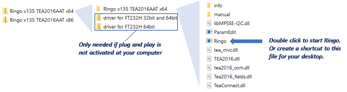
For the Ringo software to work, the FT232H driver for the USB-I2C interface needs to be installed. This installation happens automatically when you connect the interface for the first time via USB. If the driver is not installed automatically, you can use the included drivers to do this manually (a video on the get started page shows how to do this).
The Ringo program needs no installation. It can be started by double-clicking on Ringo.exe. Keep the other files and folders in the same directory because Ringo makes use of it.
3.2 User Manual and Tutorial Videos for the Ringo Software
A user manual and videos are included in the Ringo GUI software for easy access to get familiar with using the software and getting to know the functions that are available.
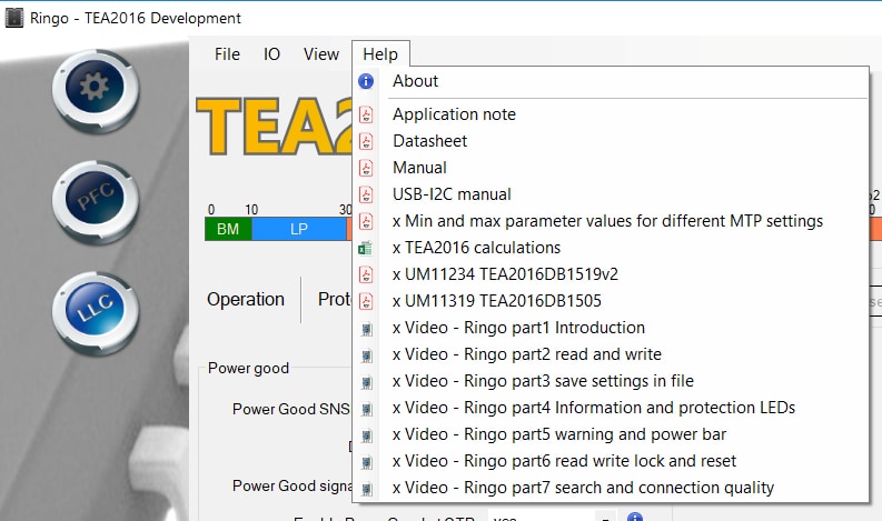
Videos are available in Ringo for viewing on your local video player or via the NXP website in your browser:
- Introduction
- Read and write
- Information and protection
- Save settings in file
- Warning and power bar
- Read write lock and reset
- Search and connection quality
The videos are available at: TEA2016AAT
4. Configure Hardware
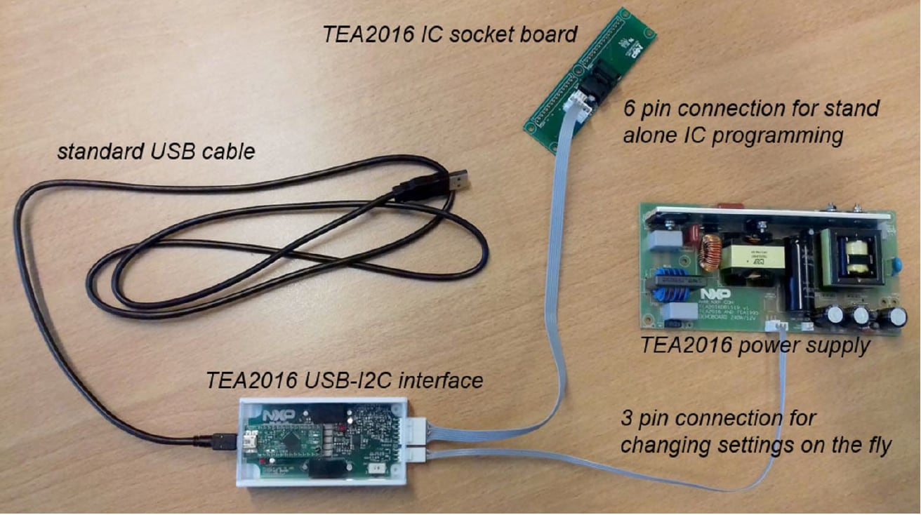
Power supply setup:
The TEA2016DB1519v2 demo board contains a TEA2016AATdev sample that can communicate via I2C during operation. It is connected to the interface with a 3-pin connection.
IC programming board setup:
Connecting a TEA2016DB1561 with a 6-pin cable provides reading or programming for TEA2016AAT ICs. If a TEA2016AATdev IC version is used, connect the 3-pin cable as well.
The switch on the interface selects the 3-pin or 6-pin connection.
4.1 Additional Board Support
Refer to UM11234, UM11235, UM11527 and Ringo software package for additional details on the featured components and board configuration.
Videos show working with a power supply during operation and discusses programmable functions for power supply design optimization.
The videos are available at: TEA2016AAT | Digital LLC PFC Combo Controller for Resonant Power Supplies | NXP Semiconductors
Design Resources
Board Information
Support
Ringo Software
Q: Ringo.exe does not start.
- A1: The USB-I2C interface driver (FT232) needs to be installed on the computer to enable Ringo software to work.
- A2: Make sure you are using a compatible version: 32 bit or 64 bit
- A3: Ringo is made for Windows operating systems. On other operating systems you can run it via a windows emulator.
- A4: It may be necessary to connect the USB-I2C interface again (one time) after a Windows update.
Q: Can I work with Ringo without the interface connected?
- A1: Yes, when the USB-I2C interface driver (FT232) is already installed
- A2: To get started the USB-I2C interface driver (FT232) needs to be installed on the computer to enable Ringo software to work. For this the interface needs to be connected (one time) to install the driver.
Q: When I connect the USB-I2C interface it does not work.
- A1: A driver is needed to make the FT232 module operational. The driver is often automatically installed (plug and play) but sometimes a manual install is required. Several drivers are included in the Ringo zip package. Watch the video “installing USB driver manually” on the NXP website.
- A2: When you install the driver and still it does not work: completely ('delete the driver software for this device') remove the driver and select another driver included or visit the FTDI chip website for more information or driver versions.
USB - I2C Interface
Q: Can I change settings in an TEA2016AATdev (development type) IC on the power supply when the power supply is not running.
- A1: Yes. When you apply a low mains voltage of 50 Vac the IC is supplied by the HV source and can communicate via I2C. But the power supply does not start because the mains voltage is still too low.
- A2: Yes. If you (temporarily) connect an external power supply of 20 V to SUPIC, the IC is operational without starting the power supply.
Q: Can I change settings in an TEA2016AAT IC (non development type) on the power supply.
- Yes, but it is more complicated. Application note AN12330 shows how to do it in section 15.5.3.2. You cannot make changes during operation because the pins for I2C communication have a different function during operation.
Q: There is no communication with the IC.
- A1: Check if the switch on the interface is in the correct position: 3 pin or 6 pin.
- A2: Check if the correct cable is connected (or both when using the programming board)
- A3: Check if signal disturbance is blocking communication
Q: I want to make a modification or repair on the board. Is there a circuit diagram?
- A1: The circuit diagram is included in User Manual UM11235. This document is available in the help tab of Ringo.
Q: What is the function of the LEDs on the board?
- A1: The Ringo software can use them for indicating that the I2C connection is OK. The indication differs between Ringo versions. In general slow blinking indicates no communication with the IC. And fast blinking indicates correct communication with the IC.
Programming Board
Q: Which cable do I need to connect when I want to work with the programming board?
- A1: Connect both 3pin and 6pin cables and select the correct I2C channel for add period after
- A2: For a TEA2016AAT IC only the 6pin cable connection is required.
- A3: For a TEA2016AATdev IC both 3pin and 6pin cables are required.
Q: I want to add an IC socket on the board. What is a suitable type?
- A1: Provisions in the board are for a Wells CTI 652B0162215 SO16 socket.
Q: I want to measure signals or make a modification on the board. Is there a circuit diagram?
- A1: The circuit diagram is included in the Ringo help tab.
Working with Only the TEA2016DB1519 Demo Board
Q: Can I also work with TEA2016AAT without buying the I2C interface and the programming board?
- A1: Yes, you can use the TEA2016 IC in a power supply as with other IC types. In this case you make use of the IC standard parameter settings.
- A2: When you want to make use of modifying TEA2016 settings for optimizing your design, you need the software and an interface board. The kit provides all you need to get started.