Getting Started with the LPC55S69-EVK Evaluation Board
Contents of this document
-
Plug It In
-
Get Software
-
Build, Run
Sign in to save your progress. Don't have an account? Create one.
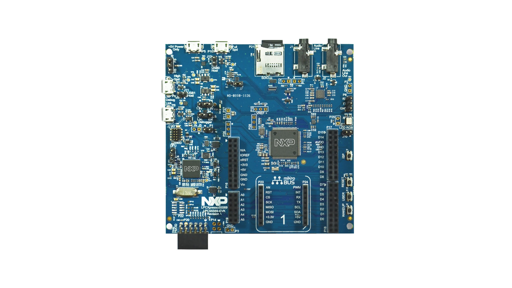
Purchase your LPC55S69-EVK
1. Plug It In
1.1 Plug It In and Demo of LPC55S69
1.3 Attach the USB Cable
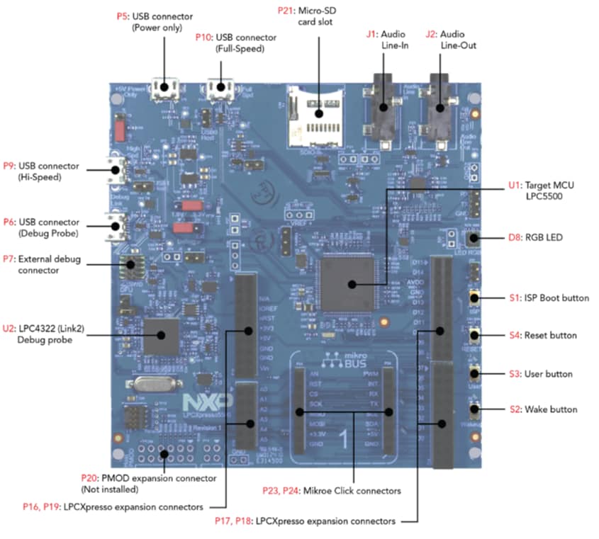
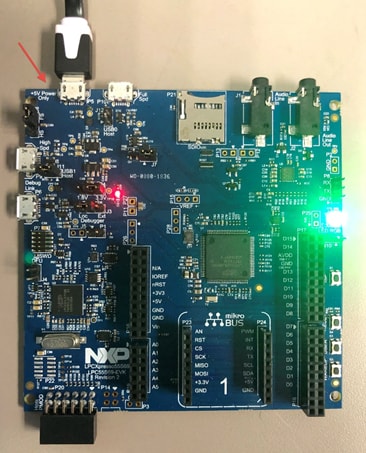
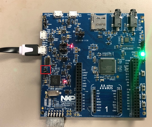
There are four micro-USB connectors on the board. One each for Full and High Speed USB, one for supplying power only and one for debug. Plug the USB cable into the one labeled +5 V Power Only as shown in the photo.
1.4 Run the Out-of-the-Box Demo
Your LPCXpresso55S69 board comes loaded with a program to verify that target MCU is running.
The application is active if the green LED in the RGB-LED flashed with a 1 Hz rate.
1.5 Switch and LED Test
- Press the [WAKEUP] button. Verify that the blue LED in the RGB-LED is constant on while pressing
- Press the [USER] button. Verify that the green LED in the RGB-LED is constant on (with only short off-flashes)
- Press the [ISP] button. Verify that the red LED in the RGB-LED is constant on while pressing
- Press the [RESET] button. Verify that the RGB-LED turns off while pressing
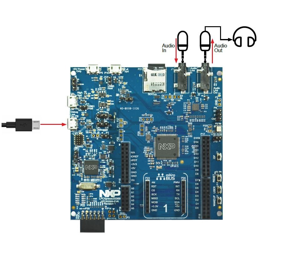
1.6 Audio Test
For this test you need:
- A line level audio source like a PC, smartphone or tablet
- A stereo audio cable to connect the audio source to the LPC55S69 board
- A stereo audio headphones or speaker
Instructions
- Plug in the audio source to the [Audio Line In] connector
- Connect headphones or speaker to the [Audio Line Out] connector
- Play audio from device connected as input
- Verify you listen to the audio on the headphones
OOB_test demo source code is available in SDK.
2. Get Software
The software and tools installation is detailed in two short videos or you can choose to follow the steps below.
2.1 Jump Start Your Design with the MCUXpresso SDK

You can also use the online SDK Builder to create a custom SDK package for the LPC55S69-EVK using the SDK builder The board name for the SDK is LPCXpresso55S69 SDK Builder.
2.2 Install Your Toolchain
NXP offers a complimentary toolchain called MCUXpresso IDE.
 Get MCUXpresso IDE
Want to use a different toolchain?

2.3 MCUXpresso Config Tools
The MCUXpresso Config Tool is an integrated suite of configuration tools that guides users in creating new MCUXpresso SDK projects, and provides pin and clock tools to generate initialization C code for custom board support. It is fully integrated into MCUXpresso or you can download a seperate tool. Click the Get MCUXpresso Config Tools below to get the Config Tools installer.
To learn more about the basic interactions between the tools wh working with either an imported MCUXpresso SDK example project or creating a new project within the IDE, watch this three-part video series.
Basic Application Development Using MCUXpresso IDE and MCUXpresso Config Tools
2.4 Debug Probe Firmware Update Using LPCScrypt
To set up your LPCXpresso55S69 for use with 3rd party tools, first install LPCScrypt in order to install the board’s device drivers. The video below shows how to use LPCScrypt to program your board’s debug probe using this utility.
2.5 Serial Terminal
Most of the MCUXpresso SDK examples set up for IAR and Keil tools use the MCU UART for printf output, and this is also an option for the MCUXpresso IDE. If you are not sure how to use a terminal application try one of these tutorials:
Not sure how to use a terminal application? Try one of these tutorials: MCUXpresso Terminal, Tera Term Tutorial, PuTTY Tutorial.
3. Build, Run
A short video is provided to walk you through this process or you can follow along the steps below.
3.1 Explore the MCUXpresso SDK Example Code
The MCUXpresso SDK comes with a long list of example applications code. To see what's available, browse to the SDK boards folder of your SDK installation and select LPCXpresso55S69.
<SDK_Install_Directory>/boards/LPCXpresso55S69
To learn more about specific example code, open the readme.txt file in an example’s directory.
3.2 Building and Debuging MCUXpresso SDK Examples
If one or more of the demo applications or driver examples sounds interesting, you're probably wanting to know how you can build and debug yourself. The Getting Started with MCUXpresso SDK guide provides easy, step-by-step instructions on how to configure, build, and debug demos for all toolchains supported by the SDK.
Use the guide below to learn how to open, build and debug an example application using the MCUXpresso IDE.
Running a Demo Using MCUXpresso IDE
Import the MCUXpresso SDK
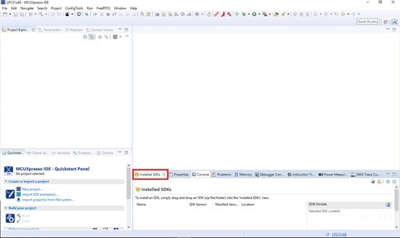
- Open the MCUXpresso IDE
- Switch to the Installed SDKs view within the MCUXpresso IDE window
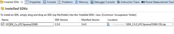
- Drag and drop the LPCXpresso55S69 SDK (zipped) file into the Installed SDKs view
- You will get the following pop-up. Click on OK to continue the import:
- The installed SDK will appear in the Installed SDKs view as shown below:
Build an Example Application
The following steps will guide you through opening the hello_world example
- Find the Quickstart Panel in the lower left-hand corner
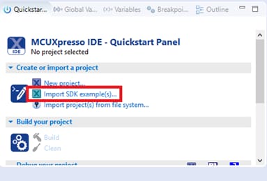
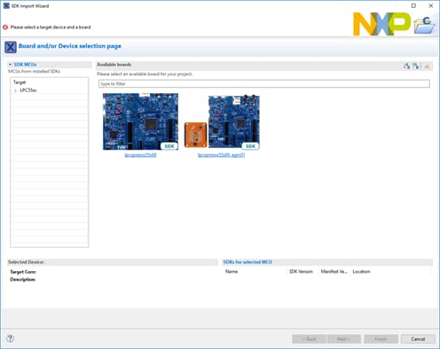
- Click on the LPCXpresso55S69 board to select that you want to import an example that can run on that board, and then click on Next
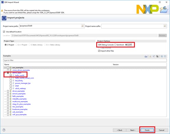
- Use the arrow button to expand the demo_apps category, and then click the checkbox next to hello_world to select that project. To use the UART for printing (instead of the default semihosting), Select UART as the SDK Debug Console checkbox under the project options. Then, click on Finish
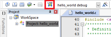
- Now build the project by clicking on the project name and then in the Quickstart Panel click on Build or press “Ctrl + b”. Or you can click on the hammer icon in the tool bar
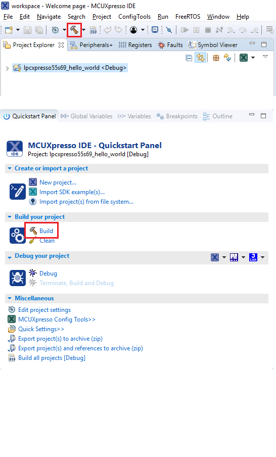
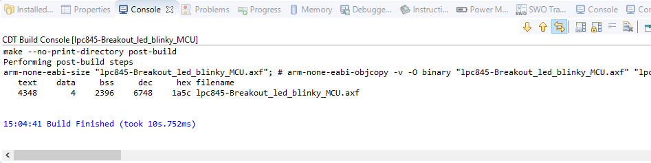
- You can see the status of the build in the console tab
Run an Example Application
- Now that the project has been compiled, you can now flash it to the board and run it
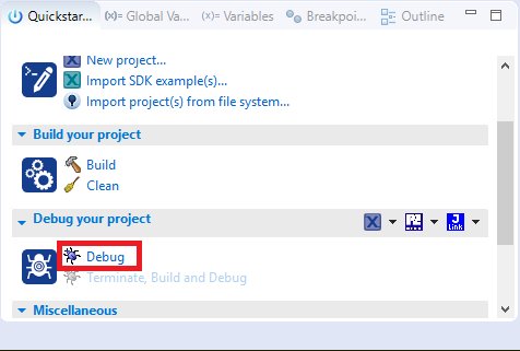
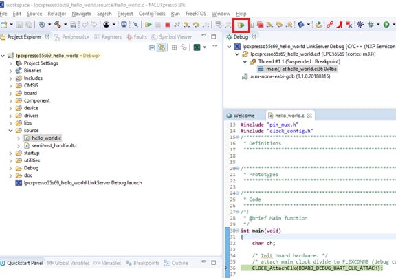
- Make sure the LPCXpresso51U68 board is plugged in, and click on Debug in the Quickstart Panel
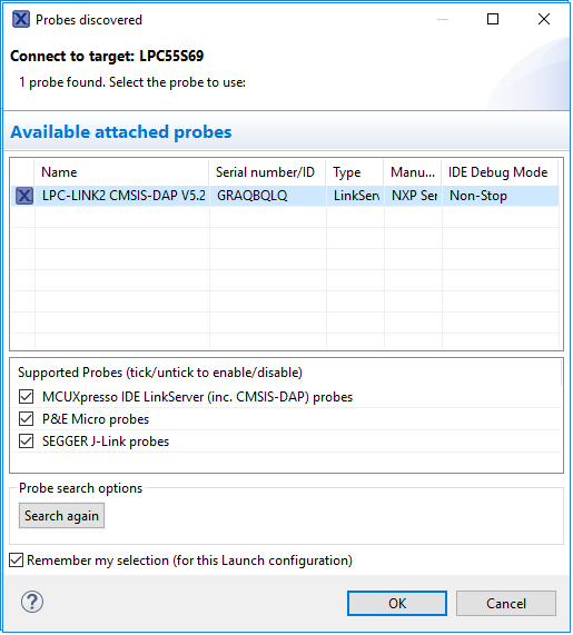
- MCUXpresso IDE will probe for connected boards and should find the CMSIS-DAP debug probe that is part of the integrated LPC-LINK2 circuit on the LPCXpresso55S69. Click on OK to continue
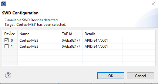
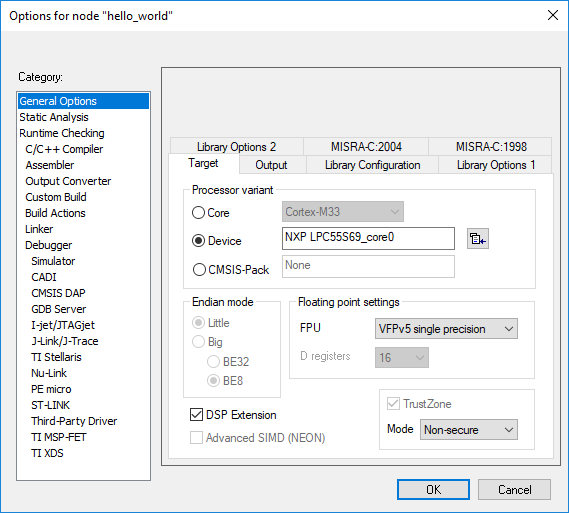
- Select the Cortex-M33 Device or Core 0 and press OK
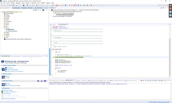
- The firmware will be downloaded to the board, and the debugger started
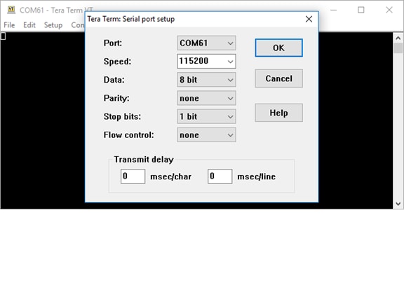
- Open a terminal program and connect to the COM port the board enumerated as. Configure the terminal with these settings:
- Start the application by clicking the "Resume" button:
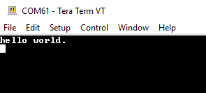
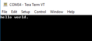
- The hello_world application is now running, and a banner is displayed on the terminal. If this is not the case, check your terminal settings and connections. You can type on the terminal console and the characters will be echoed back
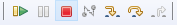
- Use the controls in the menu bar to pause, step into, and step over instructions, and then stop the debugging session by click on the Terminate icon:
Using a different toolchain?
This demo is also available for IAR and KEIL.
Running a Demo Using IAR Embedded Workbench ID
Build an Example Application
The following steps will guide you through opening the hello_world application. These steps may change slightly for other example applications as some of these applications may have additional layers of folders in their path.
- First unzip the previously downloaded SDK
-
If not already done, open the desired example application workspace. Most example application workspace files can be located using the following path:
/boards////iarUsing the hello_world demo as an example, the path is:
/boards/LPCXpresso55S69/demo_apps/hello_world/cm33_core0/iar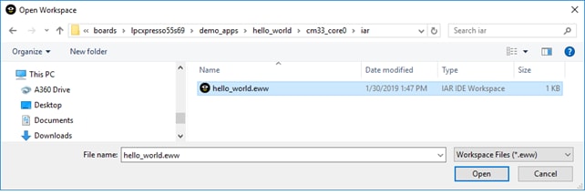
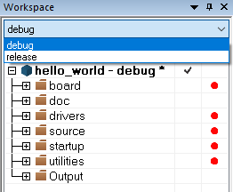
- Select the desired build target from the drop-down. For this example, select the “hello_world – Debug” target
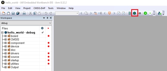
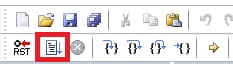
- To build the application, click the “Make” button, highlighted in red below
-
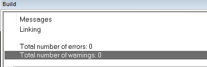
The build will complete without errors.
Run an Example Application
The LPCXpresso55S69 board comes loaded with the CMSIS-DAP debug interface from the factory. If you have changed the debug LPC-LINK2 application on your board, visit step 2.4 LPCScrypt tutorial in this getting started.
- Connect the development platform to your PC via USB cable to P6 “Debug Link.” Ensure the DFULink jumper (J4) is removed when powering the board to boot the debug probe from internal flash
-
Open the terminal application on the PC (such as PuTTY or Tera Term) and connect to the debug COM port you determined earlier. Configure the terminal with these settings:
- 115200 baud rate
- No parity
- 8 data bits
- 1 stop bit
- Click the "Download and Debug" button to download the application to the target

- The application is then downloaded to the target and automatically runs to the main() function
- Run the code by clicking the "Go" button to start the application

- The hello_world application is now running, and a banner is displayed on the terminal. If this is not the case, check your terminal settings and connections

Running a Demo Using Keil® MDK/µVision®
Install CMSIS Device Pack
After the MDK tools are installed, Cortex® Microcontroller Software Interface Standard (CMSIS) device packs must be installed to fully support the device from a debug perspective. These packs include things such as memory map information, register definitions and flash programming algorithms. Follow these steps to install the appropriate CMSIS pack.
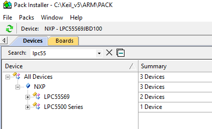
- Open the MDK IDE, which is called µVision. In the IDE, select the "Pack Installer" icon

- In the Pack Installer window, search for “LPC55S69” to bring up the LPC55S69 family. Click on the LPC55S69 name, and then in the right-hand side you’ll see the NXP::LPCXpresso55S69 _DFP pack. Click on the “Install” button next to the pack. This process requires an internet connection to successfully complete. You can do the same thing for the LPCXpresso55S69 board support package
- After the installation finishes, close the Pack Installer window and return to the µVision IDE
Build the Example Application
The following steps will guide you through opening the hello_world application. These steps may change slightly for other example applications as some of these applications may have additional layers of folders in their path.
-
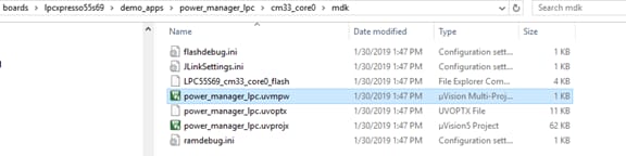
If not already done, open the desired demo application workspace in:
/boards/////mdkThe workspace file is named .uvmpw, so for this specific example, the actual path is:
/boards/LPCXpresso55S69/demo_apps/hello_world/mdk/hello_world.uvmpwFor example the power manager example project file is here
- To build the demo project, select the "Rebuild" button, highlighted in red

- The build will complete without errors
Run an Example Application
- The LPCXpresso55S69 board comes loaded with the CMSIS-DAP debug interface from the factory. If you have changed the debug LPC-LINK2 application on your board, check the LPCScrypt tutorial describe in the past section
- Connect the development platform to your PC via USB cable to P6 “Debug Link”. Ensure the DFULink jumper (
J4) is removed when powering the board to boot the debug probe from internal flash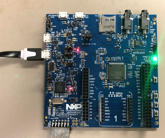
-
Open the terminal application on the PC (such as PuTTY or Tera Term) and connect to the debug COM port you determined earlier. Configure the terminal with these settings:
- 115200 baud rate
- No parity
- 8 data bits
- 1 stop bit
- After the application is properly built, click the "Download" button to download the application to the target
- Click on “Start/Stop Debug Session” to open the debug view

- Run the code by clicking the "Run" button to start the application
- The application is now running, you are going to see the RGB blue led Blinky every second
3.3 Building and Debuging MCUXpresso SDK Examples
Now its time to plug in the board to debug your project:
- Make sure the DFU jumper
J4is removed - Plug the micro USB cable from the PC into the Debug Link micro USB connector as shown
- In the Project Exporer window in MCUXpresso select your project
- In the Quick Start Panel click on Debug
- Choose the CMSIS-DAP debug interface
- Choose Core 0 for the target core
- Hit Resume to get the code running after the breakpoint at the beginning of main ()
More details can be found in the SDK getting started documents found in the SDK folder
<SDK_Install_Directory>/docs/Getting Started with MCUXpresso SDK for LPC55xx.pdf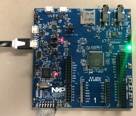
3.4 More Examples
Several examples, demos and drivers are available within the SDK to help you get started. Some common examples are listed below:
- Shell demo (UART example)
- USB examples
- NTAG I²C explorer blink
- Power manager demo
Security and Integrity
The LPC55S69 is secure-by-design and supported by secure software driving the secure System on a Chip (SoC).
| Document | Description |
|---|---|
| AN12278 LPC55S00 Security Solutions for IoT | This document lays out the differences and advances in the security systems for each LPC55Sxx MCU. |
| AN12324 LPC55Sxx usage of the PUF and Hash Crypt to AES coding | How to securely generate, store and retrieve user keys using the root key. |
| AN13094 Using FreeRTOS on LPC55Sxx Series Microcontrollers with TrustZone | How to use FreeRTOS in an ARMv8-M processor that supports TrustZone. |
| TrustZone with ARMv8-M and the NXP LPC55S69-EVK | An introduction to the ARM TrustZone security feature using MCUXpresso SDK examples and the LPC55S69 EVK. |
| How to Debug TrustZone Project on MCUXpresso IDE | Introduces debugging TrustZone on the LPCXresso55S69 board using “hello_world” as an example. |
MCUXpresso SDK Examples
Several examples, demos and drivers are available within the SDK to help you get started. Some common examples related to security are listed below.
TrustZone Examples
Several simple demonstrations are available in the TrustZone examples including a hello world, secure faults and secure gpio.
Path:
<SDK_PATH>/boards/lpcxpresso55s69/trustzone_examples</SDK_PATH>PUF Hashcrypt Crypto Demo
How to use the PUF controller which provides secure key storage and then sends a secret key via dedicated HW bus directly to Hashcrypt, which uses this key to encrypt data.
Path:
<SDK_PATH>/boards/lpcxpresso55s69/demo_apps_puf_hashcrypt_cryptoA GUI-based application provided to simple generation and provisioning of bootable executables on NXP MCU devices.
Wired Communications
| Document | Description |
|---|---|
| Using ConfigTool to Create USB Project From Start | Creating a USB project with MCUXpresso Config Tool and the LPCXpresso55S69-EVK. |
MCUXpresso SDK Examples
Several examples, demos and drivers are available within the SDK to help you get started. Some common examples related to wired communications are listed below.
Shell Demo (UART example)
Demonstrates how to implement a command line shell application.
Path:
<SDK_PATH>/boards/lpcxpresso55s16/demo_apps/shellDriver Examples
A number of driver examples exist within the SDK including GPIO, I2C, I2S, SPI and UART.
Path:
<SDK_PATH>/boards/lpcxpresso55s69/driver examplesUSB Examples
A number of USB examples for host and device operation exist within the SDK.
Path:
<SDK_PATH>/boards/lpcxpresso55s69/usb_examplesWireless Connectivity
| Document | Description | Aplication Note Software |
|---|---|---|
| AN12805 Establish Secure Connection with Private Cloud | How to create a secure embedded software project with the LPCXpresso55S69 board. | Download |
| Connecting the LPC55S69 to Amazon Web Services | Demo focused on the WIFI enablement and cloud connectivity through AWS using MCUXpresso and an Amazon Alexa. | - |
| How to Add Peripherals to AWS IOT and Alexa Skills | Step-by-step approach to adding peripherals to your AWS IOT and Alexa Skills project. | - |
MCUXpresso SDK Examples
Several examples, demos and drivers are available within the SDK to help you get started. A common example related to wireless connectivity is listed below.
NTAG I²C Explorer Blink
Shows use of NT3H2111_2211 NTAG I²C plus Connected NFC Tag with I²C Interface Chip and demonstrates basic communication with the device.
Path:
<SDK_PATH>/boards/lpcxpresso55s69/ntag_i2c_plus_examples/ntag_i2C_explorer_blinkMulticore and Hardware Acceleration
Multicore and Hardware Acceleration
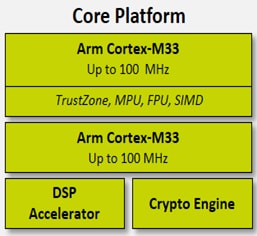
The LPC55S69 platform includes two Arm Cortex-M33 cores running up to 100 MHz. Core 0 includes TrustZone, FPU and two 64-bit Accelerators. The DSP Accelerator is called the PowerQuad DSP co-processor.
| Document | Description |
|---|---|
| AN12282 Digital Signal Processing for NXP LPC5500 Using PowerQuad | The PowerQuad co-processor is a DSP accelerator that aids the CPU cores in performing mathematical operations such as matrix calculations, filtering, and transform functions, including FFT. |
| AN12335 LPC55xx/LPC55Sxx Dual Core Communication | The LPC55xx/LPC55Sxx provides a simple hardware means called Inter-CPU Mailbox mechanism for communication. |
| AN12358 LPC55xx/LPC55Sxx Dual-Core Debug in MCUXpresso | How to debug the asymmetric dual cores of the LPC55S6x. |
| LPC55xx Multicore Applications with MCUXpresso IDE | How to create, build and debug LPC55xx multicore applications using the LPC55S69-EVK and the MCUXpresso SDK. |
MCUXpresso SDK Examples
Several examples, demos and drivers are available within the SDK to help you get started. A common example related to multicore and hardware acceleration is listed below.
Multicore Examples
Includes how to set up projects for individual cores on a multicore system.
Path:
<SDK_PATH>/boards/lpcxpresso55s69/multicore_examplesAudio
| Document | Description |
|---|---|
| AN12939 Implementation of 5.1-channel Audio Solution on LPC55xx | The on-board DSP accelerator makes the LPC55S69 very suitable for USB audio applications. |
MCUXpresso SDK Examples
Several examples, demos and drivers are available within the SDK to help you get started. Some common examples related to audio are listed below.
SDK Audio Demos
Bare metal and FreeRTOS examples that enumerate a recording or playback device.
USB Device: Audio generator, audio speaker, composite hid audio
USB Host: Audio Speaker
Path:
<SDK_PATH>/boards/lpcxpresso55s69/usb_examplesDisplay and Graphics
The SDK for the LPC55S69 includes graphic examples using the Adafruit TFT LCD shield.
| Software | Description |
|---|---|
| Graphical User Interfaces for NXP Microcontrollers | Learn more about your GUI options for NXP Microcontrollers. |
| Open Source LittlevGL GUI Library on Adafruit Touch LCDs with NXP LPC55S69-EVK | Driving Adafruit LDC Display with Capacitive Touch and MCULib. |
| LVGL Open-Source Graphics Library | LVGL is a free and open-source embedded graphic library with features that enable you to create embedded GUIs with intuitive graphical elements, beautiful visual effects and a low memory footprint. |
| GUI Guider | A user-friendly graphical user interface development tool from NXP that enables the rapid development of high quality displays with the open-source LVGL graphics library. |
| NXP emWin Libraries | NXP has partnered with SEGGER Microcontroller to offer the high performance emWin embedded graphics libraries in binary form for free commercial use with any Arm Cortex-M microcontrollers from NXP. |
| GUI Development With emWin and AppWizard | How to use the different features in AppWizard to create complete, ready-to-run projects based on emWin. |
MCUXpresso SDK Examples
Several examples, demos and drivers are available within the SDK to help you get started. Some common examples related to display and graphics are listed below.
LVGL Examples
A demo application to show littlevgl widgets.
Path:
<SDK_PATH>/boards/lpcxpresso55s69/littlevgl_examplesemWin GUI Demo
Demonstrates the graphical widgets of the emWin library.
Path:
<SDK_PATH>/boards/lpcxpresso55s69/emwin_gui_demoCamera Interfaces
Camera Interfaces
| Document | Description | Application Note Software |
|---|---|---|
| AN12868 Camera Interface in LPC55(S)xx | Introduces the camera interface, features and API routines and demo. | Download |
Motor Control
| Document | Description |
|---|---|
| FreeMASTER How To | A starting guide for engineers using FreeMASTER tool. |
| FreeMASTER 3.0 - Installation Guide | This article will walk you through the installation process of FreeMASTER 3.0. |
| FreeMASTER Four-Part Webinar Series | On-demand training provides an overview of the FreeMASTER software, its features, capabilities, available examples, application use cases and how to easily get started. |
MCUXpresso SDK Examples
Several examples, demos and drivers are available within the SDK to help you get started. Some common examples related to Motor Control are listed below.
Middleware
Path:
<SDK_PATH>/middleware/motor_controlFreeMASTER Examples
Watch variables and graphs over various interface options.
Path:
<SDK_PATH>/boards/lpcxpresso55s69/freemaster_examplesFreeMASTER Communication Driver User’s Guide
Describes the embedded-side software driver which implements a serial interface between the application and the host PC and covers the native Serial UART communication and CAN communication for the applicable devices.
Path:
<SDK_PATH>/middleware/freemaster/doc/user_guideDesign Resources
Board Documents
Chip Documents
Support
Training
| Training | Description |
|---|---|
| Basic Application Development Using MCUXpresso IDE and MCUXpresso Config Tools | This three-part video series covers the basic interactions between the MCUXpresso IDE and Config Tools when working with either an imported SDK example project or creating a new one. |
| LPC55s6X Training | Full list of on-demand training, how-to videos and webinars from NXP about this product. |
Forums
Connect with other engineers and get expert advice on designing with the LPC55 family on one of our community sites.
On this page
- 1.1
Plug It In and Demo of LPC55S69
- 1.2
Get Familiar with the Board
- 1.3
Attach the USB Cable
- 1.4
Run the Out-of-the-Box Demo
- 1.5
Switch and LED Test
- 1.6
Audio Test
- 2.1
Jump Start Your Design with the MCUXpresso SDK
- 2.2
Install Your Toolchain
- 2.3
MCUXpresso Config Tools
- 2.4
Debug Probe Firmware Update Using LPCScrypt
- 2.5
Serial Terminal