Getting Started with the i.MX 8QuadMax MEK
Contents of this document
-
Out of the Box
-
Get Software
Sign in to save your progress. Don't have an account? Create one.
Purchase your i.MX 8QuadMax/QuadPlus Multisensory Enablement Kit
1. Out of the Box
The following section describes the steps to boot the i.MX 8QuadMax MEK.
Development kit contains:
- i.MX 8QuadMax MEK board for smart devices
- USB cable (micro-B to standard-A)
- Cable -Assembly, USB 2.0 Type-A Male, USB Type-C Male, Shielded, 1m
- 12 V/11.5 A universal power supply
- Quick Start Guide
- 16 GB SD card with bootable operating system demonstration image
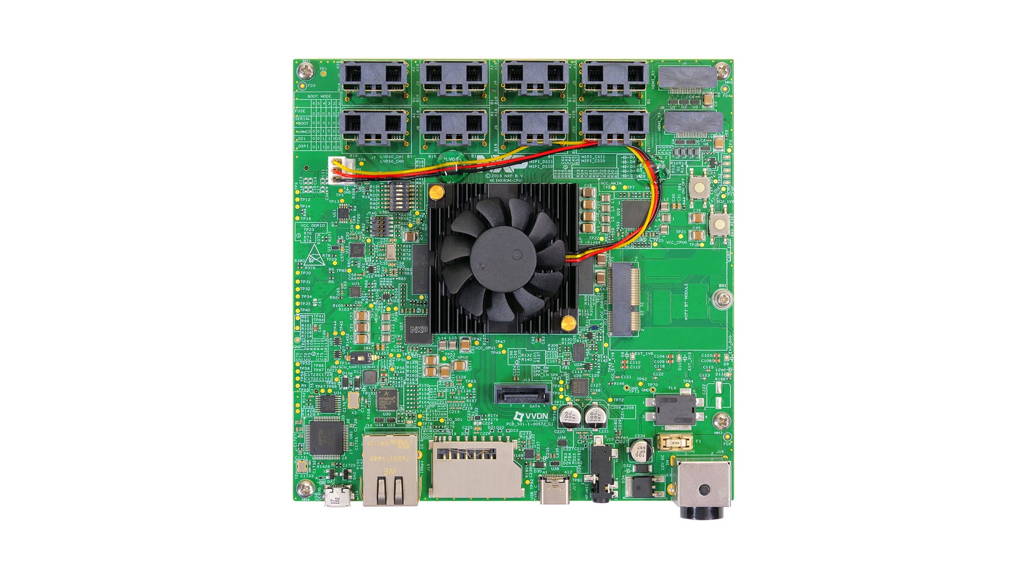
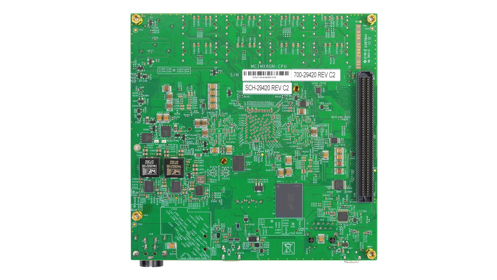
1.1 Get Familiar with the Board
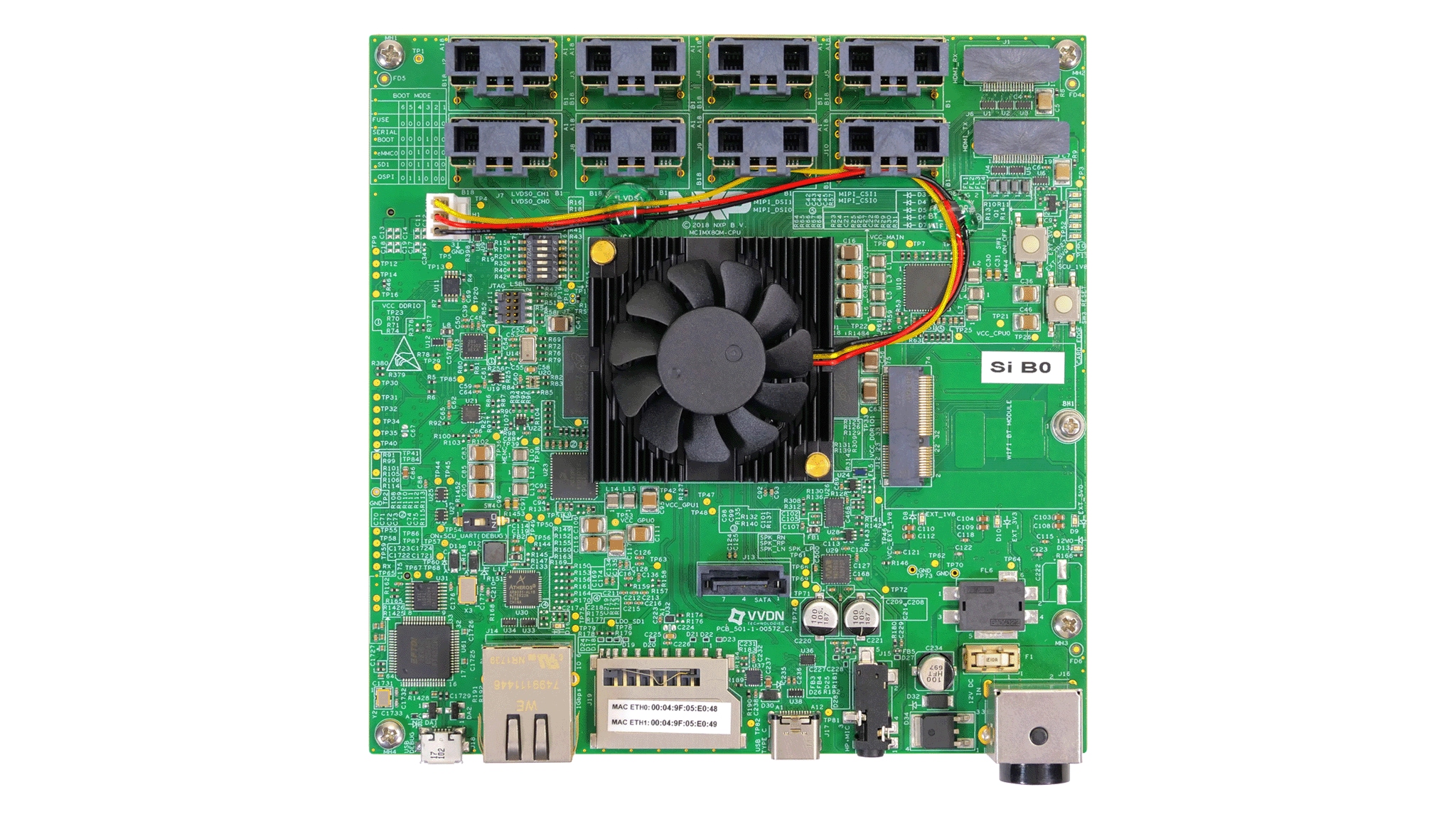
1.2 Insert the SD Card (J19)
The kit includes an SD card with a pre-built NXP Linux binary demo image. Without modifying the binary inside the SD card, booting from this SD card provides a default system with certain features for building other applications on top of Linux. The software is described in the following sections.
1.3 Connect USB Debug Cable
Connect the micro-B end of the supplied USB cable into Debug UART port
J18. Connect the other end of the cable to a host computer.
If you are not sure about how to use a terminal application, try one of the following tutorials depending on the operating system of the host machine:
1.4 Connect the HDMI Cable
To see the user interface provided with the image binary connect a monitor via the HDMI connector (J6).
1.5 Boot Switch Setup
The boot sequence is detailed in the i.MX 8QuadMax Reference Manual. In short, the boot modes of the i.MX boards are controlled by the boot configuration switches.
The switches set the boot media (depending on board, i.e. SD card, eMMC, NAND), the serial download protocol mode (SDP) or the value set on eFuses.
The SDP is also the fallback for the boot media, in other words, when the switches are configured to boot from SD card but the SD card slot is empty, or the SD card binary content is not bootable, the boot sequence continues to the SDP boot.
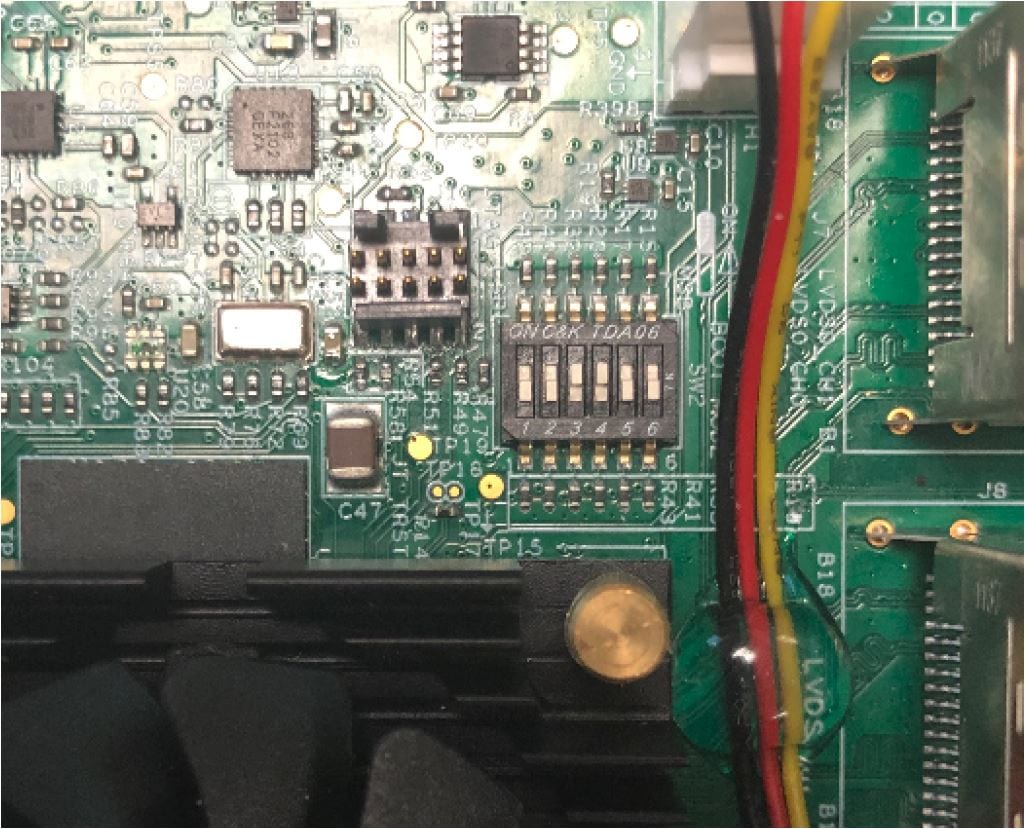
The following table lists the boot switch settings on the i.MX 8M Mini EVK board. The same information can be found on i.MX 8QuadMax Reference Manual and on silkscreen on the board near the switches.
| Boot Media |
SW2
[D1-D6]
|
|---|---|
| Fuse Boot | 000000 |
| SDP | 000100 |
| eMMC | 0001000 |
| SD1 | 001100 |
| QSPI | 011000 |
1.6 Connect Power Supply
Connect the power supply cable to the power connector (J16).
Power the board by flipping the switch (SW1).
The processor starts executing from the on-chip ROM code. With the default boot switch setup, the code reads the fuses to define the media where it is expected to have a bootable image. After it finds a bootable image, the U-Boot execution should begin automatically.
Information is printed in the smaller number serial console for the Cortex®-A53. If you do not stop the U-Boot process, it continues to boot the Linux kernel.
2. Get Software
This section is applicable ONLY if attempting to load a Linux operating system on the board.
The i.MX Linux Board Support Package (BSP) is a collection of binary files, source code, and support files that are used to boot an Embedded Linux image on a specific i.MX development platform.
Current releases of Linux binary demo files can be found on the i.MX Linux download page. Additional documentation is available in the i.MX Linux documentation bundle under the Linux sections of the i.MX Software and Development Tool.
2.1 Embedded Linux®
This section is applicable ONLY if attempting to load a Linux operating system on the board.
The i.MX Linux Board Support Package (BSP) is a collection of binary files, source code, and support files that are used to boot an Embedded Linux image on a specific i.MX development platform.
Current releases of Linux binary demo files can be found on the i.MX Linux download page. Additional documentation is available in the i.MX Linux documentation bundle under the Linux sections of the i.MX Software and Development Tool.
2.2 Overview
Before the Linux OS kernel can boot on an i.MX board, the Linux kernel is loaded to a boot device (SD card, eMMC and so on) and the boot switches are set to boot that device.
There are various ways to download the Linux BSP image for different boards and boot devices.
For this getting started guide, only a few methods to transfer the Linux BSP image to an SD card are listed. Experienced Linux developers can explore other options.
2.3 Download an NXP Linux BSP Pre-Built Image
The latest pre-built images for the i.MX 8QuadMax MEK are available on the Linux download page under the most current version on Linux.
The pre-built NXP Linux binary demo image provides a typical system and basic set of features for using and evaluating the processor. Without modifying the system, the users can evaluate hardware interfaces, test SoC features, and run user space applications.
When more flexibility is desired, an SD card can be loaded with individual components (boot loader, kernel, dtb file, and rootfs file) one-by-one or the .sdcard image is loaded and the individual parts are overwritten with the specific components.
2.4 Burn NXP Linux BSP Image Using Universal Update Utility (UUU)
In addition to the connections from Out of box chapter, connect the J17 to the host machine using the proper USB cable.
Turn off the board. Consult Boot Switch Setup and configure the board to boot on SDP (Serial Download Protocol) mode.
Depending on the OS used in the host machine, the way to transfer the Linux BSP image onto an SD card can vary.
Linux®
Install UUU on Linux Distro
Download the latest stable files from UUU GitHub page. An extensive tutorial for UUU can be found in UUU GitHub Home page.
- uuu
- libusb1 (via apt-get or any other package manager)
Burn the NXP Linux BSP Image to the Board
By default, this procedure flashes the image to the SD card flash. Check the UUU GitHub page for reference on how to flash the image to other devices.
Open a terminal application and change directory to the location where uuu and the latest Linux distribution for i.MX 8QuadMax MEK are located. Add execution permission to the uuu file and execute it. Uuu waits for the USB device to connect
$ chmod a+x uuu $ sudo ./uuu <kernel_version>_images_<SOC>.zipTurn on the board, uuu starts to copy the images to the board.
When it finishes, turn off the board, and consult Boot Switch Setup to configure the board to boot from SDcard.
Windows™
Install UUU on Windows
Download the latest stable files from UUU GitHub page. An extensive tutorial for UUU can be found in UUU GitHub Home page.
- uuu.exe
- Serial USB drivers (depending on your board and Windows installation)
Burn the NXP Linux BSP Image to the Board
By default, this procedure flashes the image to the SD card flash. Check the UUU GitHub page for reference on how to flash the image to other devices.
Open the command prompt application and navigate to the directory where the uuu.exe file and the Linux release for the i.MX 8QuadMax MEK are located.
> uuu.exe <kernel_version>_images_<SOC>.zipTurn on the board, uuu starts to copy the images to the board.
When it finishes, turn off the board, and consult Boot Switch Setup to configure the board to boot from SDcard.
Minicom Tutorial
Serial Communication Console Setup
On the command prompt of the Linux host machine, run the following command to determine the port number:
$ ls /dev/ttyUSB*The smaller number is for Arm® Cortex®-A53 core and the bigger number is for Arm® Cortex ®-M4 core.
Minicom
Use the following commands to install and run the serial communication program (minicom as an example):
- Install Minicom using Ubuntu package manager.
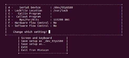
$ sudo apt-get install minicom - Launch Minicom using a console window using the port number determined earlier.
$ sudo minicom -s - Configure Minicom as show in Figure 3
- The next step is to Connect the HDMI cable.
Tera Term Tutorial
Serial Communication Console Setup
The FTDI USB-serial chip on i.MX 8QuadMax creates one serial port. Assume that the port is
COM9. This represents the serial console communication from Arm® Cortex®-A53 core. The serial-to-USB drivers are available to download here .
Tera Term
Is an open source terminal emulation application. This program displays the information sent from the NXP development platform’s virtual serial port.
- Download Tera Term. After the download, run the installer and then return to this webpage to continue
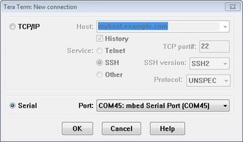
- Launch TeraTerm. The first time it launches, it shows the following dialog. Select the serial option. Assuming your board is plugged in, there should be a COM port automatically populated in the list
- Configure the serial port settings (using the
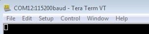
COMport number identified earlier) to115200baud rate,8data bits, no parity and1stop bit. To configure the serial port, go to Setup → Serial Port and change the settings - Verify that the connection is open. If connected, Tera Term shows something like below in its title bar
- The next step is to Connect the HDMI cable
PuTTY Tutorial
Serial Communication Console Setup
The FTDI USB-serial chip on i.MX 8QuadMax creates one serial port. Assume that the port is COM9. This represents the serial console communication from Arm® Cortex®-A53 core. The serial-to-USB drivers are available here
PuTTY is a terminal-emulation application. This program displays the information sent from the NXP development platform's virtual serial port.
- Download PuTTY After the download, run the installer and then return to this webpage to continue.
- Launch PuTTY by either double clicking on the executable file you downloaded or from the Start menu, depending on the type of download you selected
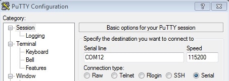
- Configure In the window that launches. Select the Serial radio button and enter the
COMport number that you determined earlier. Also enter the baud rate, in this case115200 - Click Open to open the serial connection. Assuming the board is connected and you entered the correct
COMport, the terminal window opens. If the configuration is not correct, PuTTY alerts you - The next step is to Connect the HDMI cable
Design Resources
Board Documents
In the case of i.MX 8QuadMax MEK the following documents are available.
| Document | Description |
| Board Schematics | The i.MX 8QuadMax MEK electric schematic files. |
| i.MX 8QuadMax MEK Hardware User Guide | The purpose of this document is to help hardware engineers design and test their imx8qm series processor-based designs. It provides information on board layout recommendations, design checklists to ensure first-pass success, and ways to avoid board bring-up problems. It also provides information on board-level testing and simulation such as using BSDL for board-level testing, using the IBIS model for electrical integrity simulation and more. |
Chip Documents
SoC Documents
In the case of i.MX 8QuadMax SoC the following documents are available.
| Document | Description |
| i.MX 8QuadMax DataSheet | Describes the SoC physical and electrical characteristics, the part number meaning. |
| i.MX 8QuadMax Reference Manual | Lists what the SoC supports, the registers and the memory map. Describes the features, workflow, the boot flow, and the meaning of each register's bits. |
| i.MX 8QuadMax ERRATA | List the hardware issues for that SoC. It may be an Arm core or an i.MX core issue. It may or may not have a workaround. |
| i.MX 8QuadMax Security Reference Manual | Sing-in to request access to the i.MX 8QuadMax Security Reference Manual. The link to download is sent in the email. |
Software Documents
For i.MX 8QuadMax MEK the following BSPs are available.
- Linux Kernel distribution using the Yocto Project: For details, see the documentation in i.MX 8QuadMax MEK BSP Linux documents
- Android: For details, see the documentation in i.MX 8QuadMax MEK BSP Android documents
Each BSP has a set of documents, in the next tables all the BSP documentation is described. The order the documents appear in the table is the recommended read order.
| Document | Description |
| Linux Doc Bundle | Downloads all the i.MX Linux BSP files listed here as one tarball. |
| i.MX Linux Release Notes | If you do not know where to start, start here! It lists the supported boards, the supported features, the packages versions and the known issue list. |
| i.MX Linux Users Guide | Describes the steps to download, build and deploy the i.MX Linux BSP. For example, detail how to configure, build, and deploy U-Boot booting from different medias. |
| i.MX Yocto Project Users Guide Linux | Describes the steps to download, build, deploy and configure the Yocto Project metadata, and build an image. |
| i.MX BSP Porting Guide Linux | Describes the steps to port the i.MX Linux BSP to a custom board or platform. |
| i.MX Reference Manual Linux | Describes the i.MX BSP Linux Kernel drivers, features, and how to configure the kernel. It also describes how drivers works. |
| i.MX Graphics Users Guide Linux | Describes how to test and configure the GPU for custom use cases. |
| Document | Description |
| Android Doc Bundle | Downloads all the i.MX Android BSP files listed here as one tarball. |
| Android Release Notes | If you do not know where to start, start here! It lists the supported boards, the supported features, the packages version, and the known issue list. |
| Android Quick Start Guide | Describes the board, the files in the i.MX Android BSP, how to deploy and foot the images using different displays. |
| Android Users Guide | It is the document with instructions on how to set a Linux machine to build Android, how to build, configure, and, deploy the i.MX Android BSP. |
| i.MX BSP Porting Guide Android | Describes the steps to port the i.MX Android BSP to a custom board or platform; including steps to configure multimedia and display. |
| i.MX Graphics Users Guide Android | Describes how to test and configure the GPU for custom use cases. |
| Android Frequently Asked Questions | Lists frequently asked question related to Android. |
On this page
- 1.1
Get Familiar with the Board
- 1.2
Insert the SD Card (J19)
- 1.3
Connect USB Debug Cable
- 1.4
Connect the HDMI Cable
- 1.5
Boot Switch Setup
- 1.6
Connect Power Supply