Getting Started with the MCIMX8M-EVK
Contents of this document
-
Out of the Box
-
Embedded Linux®
-
Embedded Android
-
MCUXpresso SDK
Sign in to save your progress. Don't have an account? Create one.
Purchase your i.MX 8M Evaluation Kit
1. Out of the Box
The following instructions will guide you on how to boot the preloaded Android image on the i.MX 8M Evaluation Kit.
The development kit contains:
- i.MX8MQuad EVK board for smart devices
- USB cable (micro-B to standard-A)
- Cable -Assembly, USB 3.0 Type-A Male, USB micro-B Male, Shielded, 1 m
- Cable -Assembly, USB 2.0 Type-A Male, USB-Type C Male, Shielded, 1 m
- 12 V/5 A universal power supply
- Quick Start Guide
- Android BSP flashed into the eMMC
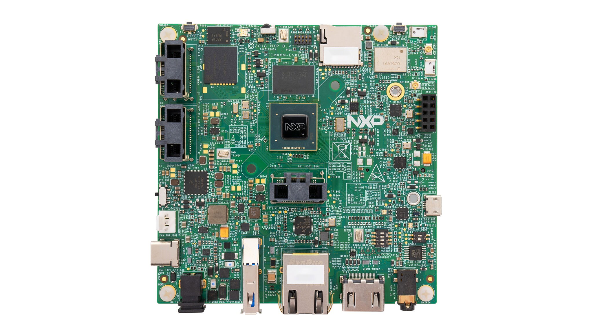
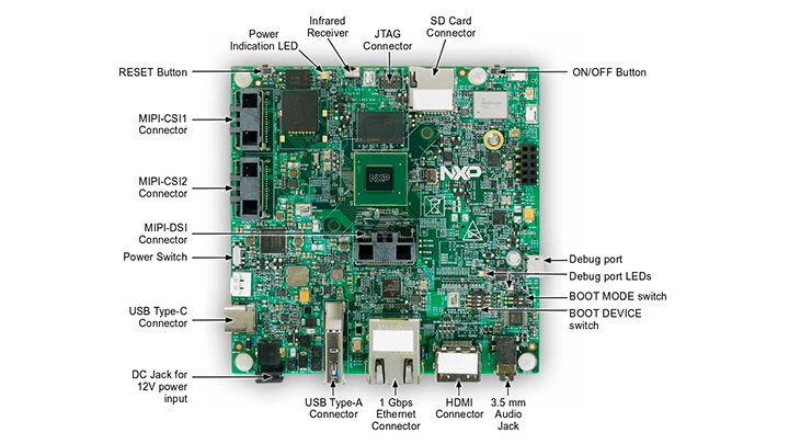
1.1 Get Familiar with the Board
1.2 Boot from eMMC
The i.MX8MQuad EVK comes with a pre-built NXP Android binary demo image flashed on the eMMC. Without modifying the binary inside, booting from the eMMC provides a default system with certain features for building other applications on top of Android.
To understand more about NXP’s Embedded Linux®, Embedded Android™, or MCUXpresso SDK, continue reading the next sections.
1.3 Connect USB Debug Cable
Connect the micro-B end of the supplied USB cable into Debug UART port
J901. Connect the other end of the cable to a host computer.
If you are not sure about how to use a terminal application, try one of the following tutorials depending on the operating system of the host machine: Minicom Tutorial, Tera Term Tutorial, PuTTY Tutorial.
1.4 Connect the HDMI Cable
To see the user interface provided with the image binary connect a monitor via the HDMI connector (J1001).
1.5 Boot Switch Setup
By default, all the boot switches are configured to zero position. With the SW801 switch on eMMC boot mode, the board boots from the eMMC.
The boot modes of the i.MX boards are controlled by the boot configuration boot switches on the board.
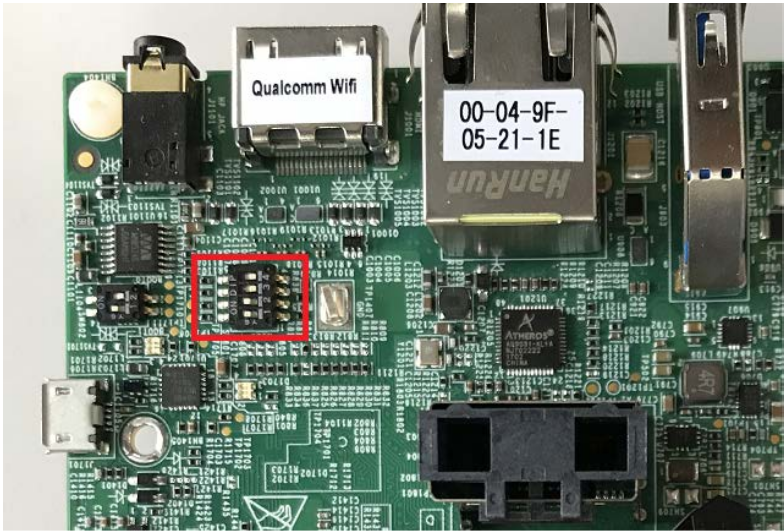
The following table lists the boot switch settings (which takes priority in boot process) for booting from the eMMC on the i.MX8MQuad EVK board.
| Switch | D1 | D2 | D3 | D4 |
|---|---|---|---|---|
SW801 |
OFF | OFF | ON | OFF |
SW802 |
ON | OFF | - | - |
1.6 Connect Power Supply
Connect the plug of the 12 V power supply to the DC power jack J902. Power on the EVK board by sliding power switch SW701 to ON.
Power the board by flipping the switch (SW701). The processor starts executing from the on-chip ROM code. With the default boot switch setup, the code reads the fuses to define the media where it is expected to have a bootable image. After it finds a bootable image, the U-Boot execution should begin automatically.
Information is printed in the smaller number serial console for the Cortex-A53 (COM9 on Windows as an example and /dev/ttyUSB* on Linux). If you do not stop the U-Boot process, it continues to boot the Linux kernel.
1.7 Android Has Booted
During the boot process, the Android logo appears on the HDMI display. Note that the HDMI output resolution is 1080P fixed — to change it, check the Android Documentation.
The Android UI can be seen after the boot process is finished. You can start operating with the mouse.
2. Embedded Linux®
This section is applicable only if attempting to load a Linux operating system on the board.
The i.MX Linux Board Support Package (BSP) is a collection of binary files, source code, and support files that are used to boot an Embedded Linux image on a specific i.MX development platform.
Current releases of Linux binary demo files can be found in the i.MX Linux download page. The Linux User's Guide and Linux Reference Manual provide additional information. Additional documentation can be found in the i.MX Linux documentation bundle, or under the Linux sections on the i.MX Software and Development Tools.
2.1 Overview
Before the Linux OS kernel can boot on an i.MX board, the Linux image is copied to a boot device (SD card, eMMC and so on) and the boot switches are set to boot that device.
There are various ways to download the Linux BSP image for different boards and boot devices.
For this getting started guide, only a few methods to transfer the Linux BSP image to an SD card are listed. Experienced Linux developers can explore other options.
Depending on the OS used in the host machine, the way to transfer the Linux BSP image onto an SD card can vary.
Choose an option below for detailed instructions
Linux
Download an NXP Linux BSP pre-built image
A .sdcard file is a disk image that is flashed directly into any SD card. This is the simplest way to load all necessary components required to boot the i.MX8MQuad EVK board. The latest pre-built images for the i.MX8MQuad EVK is available on the Linux download page.
The pre-built NXP Linux binary demo image provides a typical system and basic set of features for using and evaluating the processor. Without modifying the system, users can evaluate hardware interfaces, test SoC features, and run user space applications.
To bring up the board and run Linux, four elements are needed on the boot image:
- Bootloader (U-Boot)
- Linux kernel image (
zImage) - A device tree file (
.dtb) for the board being used - A root file system (
rootfs) for the particular Linux image
The .sdcard images contain these four elements in a single file.
When more flexibility is desired, an SD card can be loaded with individual components (bootloader, kernel, dtb file and rootfs file) one-by-one or the .sdcard image is loaded, and the individual parts are overwritten with the specific components.
Burn an SD card disk image from a Linux host computer
Once the BSP package is downloaded from the Linux download page, ensure that a pre-built SD card image built specifically for the i.MX8MQuad EVK board is in the compressed file. The SD card image is named:
<image_name>-<board name>.sdcardConnect the SD/MMC card reader with a SD card to your host machine running the Linux OS.
The Linux OS kernel running on the host assigns a device node to the SD/MMC card reader.
To identify the device node assigned to the SD/MMC card, perform the following command in the host computer:
$cat /proc/partitionsThe instructions below will permanently delete existing content on the SD card and are dangerous to your PC if run incorrectly. If you have questions or would like further details, consult the i.MX Linux User's Guide .
Run the following command to copy the SD card image to the SD/MMC card. Change /dev/sdX below to match the one used by the SD card.
$sudo dd if=<image name>.sdcard of=/dev/sdX bs=1M && sync<To setup the partition manually, read section 4.3.3 in i.MX Linux User's Guide .
To load individual components separately when the full SD card image is not used, refer to sections 4.3.4-4.3.6 in i.MX Linux User's Guide .
With the source code and documentation, the users can customize the Linux image built for the device. For example, add or remove system components.
Build your own Linux BSP image (optional)
To build an NXP Linux BSP image, you can obtain the source code from the i.MX GitHub repository .
Detailed instructions on how to build an image are available in the Linux User's Guide .
The Yocto Project
As an option, NXP provides a framework to build custom images. The Yocto Project is the framework of choice with NXP professional support to build custom images that are used for booting a Linux kernel, although other methods can be used.
Details on how to set up the Yocto Project go beyond this getting started guide. For details, refer to the NXP Yocto User's Guide .
Windows
Burn NXP Linux BSP image using Manufacturing Tool
The Manufacturing Tool, named MFGTool, is NXP tool of choice to load images on i.MX boards from a Windows OS host computer. The MFGTool is used to download images to different devices on i.MX board.
Perform the following steps to flash the board images:
- The compressed file is found in the pre-built Linux BSP image download bundle
- Unzip the
L4.9.88_2.0.0-ga_mfg-tools.tar.gzfile to a selected location. This file includes two different MFGTool configurations, one with the rootfs images and one without it. For this tutorial, unzip themfgtools-with-rootfs.zipwhich creates a directory which is namedMFGTool- Dirin this example - Ensure that the files are inside the directory
MFGTool-Dir/Profiles/Linux/OS Firmware/filespath. If there are no files, copy the files from the pre-built images - Change the board's
SW802(boot mode) to01(from bit 1 to bit 2) to enter flash mode - Power on the board. Use USB cable on the board OTG port, and connect a computer running Windows OS with the board
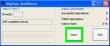
- Double-click the
*.vbsfile according to the target device as shown in the following table -
Click Start to start flashing images
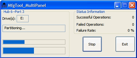
The figure below shows flashing in progress, and the status bar shows the flash status. The flash may take one to two minutes depending on the host machine
The figure below shows the tool when the flash is complete
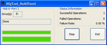
- Click Stop and disconnect the USB cable
- Change
SW801(boot mode) to1100andSW802to10to switch the board back toJ1601boot mode
Note: There are two USB micro ports in i.MX8MQuad EVK board: USB to UART and USB OTG. The USB to UART can be referenced as debug UART, and the USB OTG can be referenced as USB in the hardware image above. The debug UART can be used to watch the log of the hardware boot processing.
The SD card should be plugged in after the board is powered on
| Target device and boot storage VBS file | *VBS file |
|---|---|
| i.MX8MQuad EVK | mfgtool2-yocto-mx8-evk-sdcard-sd2.vbs |
3. Embedded Android
This section describes the boot process of loading the i.MX8MQuad EVK board with an Embedded Android system image and introduces how to build the software components that create your own system image. For details on building the Android platform, see the Documentation .
The current release includes Demo Images, Source Code and Documentation. These can also be found under Android section of the i.MX Software and Development Tools.
3.1 Overview
The storage devices on the development system (MMC/SD or NAND) must be programmed with the U-Boot bootloader. The boot process determines which storage device to access based on the switch settings. When the bootloader is loaded and begins execution, the U-Boot environment space is then read to determine how to proceed with the boot process.
The images can come from pre-built release packages or be created from source code. Regardless of how you obtain them, all Android images contain the following components:
-
U-Boot image:
u-boot.imx -
Boot image:
boot.img -
Android system root image:
system.img -
Recovery root image:
recovery.img
For more information about the Android BSP refer to the Android User's Guide .
Depending on the OS used in the host machine, the way to transfer the Android BSP image onto an SD card can vary.
Choose an option below for detailed instructions
Linux
Download NXP Android BSP Image
The pre-built NXP Android demo image provides a default system with certain features for the purpose of evaluation. Without modifying the system, users can perform some basic operations, and interact with the system to test hardware interfaces and develop a software application in the user space.
The pre-built images from the package are categorized by boot device and put in the directory with the device name. The latest pre-built image files can be found in Android section on the i.MX Software and Development Tools or in the demo images downloader link.
Loading images and partition onto an SD card
Once you download the pre-built images, the script below can be used to partition an SD card:
$cd ${MY_ANDROID}/
                $sudo ./device/fsl/common/tools/fsl-sdcard-partition.sh -f imx8mq /dev/sdX
In /dev/sdX the X is the disk index from 'a' to 'z'. That may be different
on each computer running Linux OS.
Different SD card sizes require different partition scripts:
-
If the SD card is 8 GB, use:
$sudo ./device/fsl/common/tools/fsl-sdcard-partition.sh -f imx8mq /dev/sdX -
If the SD card is 16 GB, use:
$sudo ./device/fsl/common/tools/fsl-sdcard-partition.sh -f imx8mq -c 14 /dev/sdX -
If the SD card is 32 GB, use:
$sudo ./device/fsl/common/tools/fsl-sdcard-partition.sh -f imx8mq -c 28 /dev/sdX - Unmount all the SD card partitions before running the script:
$umount
                        /dev/sdX
Copy the related bootloader, boot image, system image, recovery image, GPT table image, and vendor image in your current directory.
This script requires to install the simg2img tool on the computer. simg2img
is a tool that converts the sparse system image to raw system image on the Linux OS host computer.
The android-toolsfsutils package includes the simg2img command for Ubuntu Linux OS.
Build your own Android BSP Image (Optional)
To build the Android source files a host computer running Linux OS is required. Ubuntu 14.04 (64-bit) version is the most tested OS for the Android NXP BSP Release.
Check whether you have all the necessary packages installed for an Android build. See "Setting up your machine" on the Android website Documentation .
In addition to the packages requested on the Android website, refer to Android User's Guide to install the additional packages. Which can be found inside the Documentation bundle.
Source Code
Get the Android source code from Google repository using the manifest and script provided inside the source code package.
$sudo apt-get install repo
                $source ~/imx-o8.1.0_1.3.0_8mq_ga/imx_android_setup.sh
By default, the imx_android_setup.sh script will create the source code build
environment in the folder ~/android_build.
$export MY_ANDROID=~/android_buildBuild
The build configuration command lunch can be issued with an argument strings.
<build name>-<build type>The following is an example on how to build the Android image with user type for the i.MX8MQuad EVK board:
$cd ~/myandroid
                $source build/envsetup.sh
                $lunch evk_8mq-user
                $make 2>&1 | tee build-log.txt
When the make command is complete, the build-log.txt file contains the
execution output. Check for any errors.
The default configuration in the source code package takes internal eMMC as the boot storage. To change to SD card, refer to Android User’s Guide which can be found inside the Documentation bundle.
There are several additional information on how to build, customize and change the Android source code in the documents present in Documentation bundle.
Windows
Download UUU on Windows
Download the latest stable files from UUU GitHub page . An extensive tutorial for UUU can be found here .
- uuu.exe
- libusb-1.0.dll
- Serial USB drivers (depending on your board and Windows installation)
Download the Latest Android Images
Download the Android demo files from NXP.com.
Extract the downloaded file into a known directory.
Burn the NXP Linux BSP Image to the Board
Copy the file named uuu from section Download UUU on Windows into the extracted Android
demo directory.
Open Command Prompt and navigate to the extracted Android demo directory
> uuu.exe uuu-android-mx8mm-evk-sd.lstInsert an SD card on connector J1701. Turn on the board in serial download mode,
uuu starts to copy the images to the board. To put the board in serial download mode
follow the instructions on the Boot Switch Setup section.
When it finishes, turn off the board, and consult Boot switch setup to configure the board to boot from SD card.
4. MCUXpresso SDK
The MCUXpresso Software Development Kit (MCUXpresso SDK) provides comprehensive software source code to be executed in the i.MX8MQuad M4 core. If you do not wish to enable the Cortex-M4 on i.MX8MQuad at this moment you can skip this section.
4.1 Overview
The MCUXpresso SDK is designed for the development of embedded applications for Cortex-M4 standalone or collaborative use with the A cores. Along with the peripheral drivers, the MCUXpresso SDK provides an extensive and rich set of example applications covering everything from basic peripheral use case examples to demo applications. The MCUXpresso SDK also contains RTOS kernels, device stack, and various other middleware to support rapid development.
Depending on the OS used in the host machine, the way to build and deploy the demos can vary.
Choose an option below for detailed instructions
Linux
Download MCUXpresso SDK on Linux
Current releases of the MCUXpresso SDK and source code can be found at MCUXpresso SDK Builder .
To download the MCUXpresso SDK for i.MX8MQuad, follow these steps:
-
Click on "Select Development Board"
-
Select
evkmimx8mqunder "Select a Device, Board, or Kit" and click on "Build MCUXpresso SDK" on the right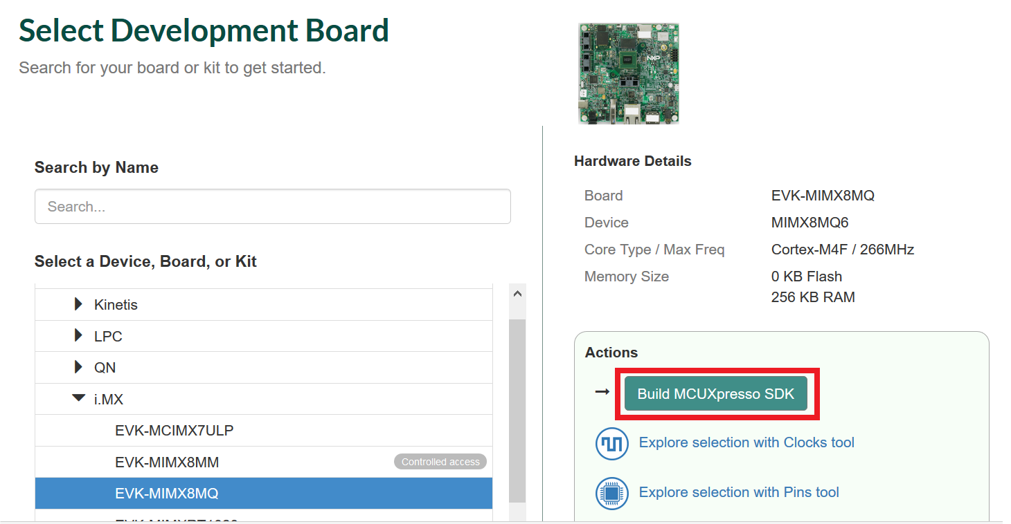
-
Select "Host OS" as
Linux -
Select "Toolchain/IDE" as
GCC Arm Embedded -
Click on "Select Optional Middleware", "Select All" and hit "Save changes"
-
Click on "Request Build"
-
Wait for the SDK to build and download the package
Build MCUXpresso SDK and Install Toolchain on Linux
-
Download and run the installer from
launchpad.net/gcc-arm-embedded. This is the actual toolchain. The toolchain includes the compiler, linker, and so on. The GCC Toolchain should correspond to the latest supported version, as described in the MCUXpresso SDK Release Notes found in the package already downloaded -
Export the toolchain location as
ArmGCC_DIR$ export ArmGCC_DIR=/usr -
Ensure that
cmakeis installed:
$ sudo apt-get install cmake
$ sudo apt-get install gcc-arm-none-eabi
Build MCUXpresso SDK
-
Change the directory of the command window to the demo armgcc directory and run the build command:
$ <install_dir>/boards/evkmimx8mq/demo_apps/<demo_name>/armgcc</demo_name></install_dir>$ ./build_all.sh -
There are two project configurations (build targets) supported for each MCUXpresso SDK project:
- Debug: Compiler optimization is set to low, and debug information is generated for the executable. This target is selected for development and debug
- Release: Compiler optimization is set to high, and debug information is not generated. This target is selected for final application deployment
Note: There are script files provided to build both configurations. For this example, the
Debugtarget is built andbuild_debug.shis typed on the command line. If theReleasetarget is desired, typebuild_release.shinstead. -
The previous command generates the debug and release binaries (
sdk20-app.bin). These files are in the debug and release folders - Copy the bootable image
sdk20-app.binto the boot partition of the SD card
Run applications using U-Boot
This section describes how to run applications using an SD card and pre-built U-Boot image for i.MX processor.
-
Following the steps on the Embedded Linux® tab, prepare an SD card with a pre-built U-Boot and a Linux image from Linux BSP package for the i.MX8MQuad processor. If you have already loaded the SD card with a Linux image, you can skip this step
- Insert the SD card in the host computer (Linux or Windows), and copy the application image (for example
sdk20-app.bin) to the FAT partition of the SD card - Safely remove the SD card from the PC
- Insert the SD card to the target board. Make sure to use the default boot SD slot and double check the Boot Switch Setup. The default configuration of the validation board boots from
J1601, and on EVK board there is only one SD slot which is used for boot -
Connect the
DEBUG UARTslot on the board with your PC through the USB cable. The Windows OS installs the USB driver automatically, and the Ubuntu OS will find the serial devices as well - Open a second terminal emulator on the i.MX8MQuad EVK board’s second enumerated serial port. This is the Cortex-M4’s serial console. Set the speed to 115,200 baud rate, 8 data bits, no parity, and power on the board
-
Power up the board and stop the boot process by pressing any key before the U-Boot countdown reaches zero. At the U-Boot prompt on the first terminal emulator, type the following commands to U-Boot
=> fatload mmc 1:1 0x7e0000 sdk20-app.bin=> bootaux 0x7e0000These commands copy the image file from the first partition of the SD card into the Cortex-M4's memory and release the Cortex-M4 from reset
Windows
Download MCUXpresso SDK on Windows
Current releases of the MCUXpresso SDK and source code can be found at MCUXpresso SDK Builder .
To download the MCUXpresso SDK for i.MX8MQuad, follow these steps:
-
Click on "Select Development Board"
-
Select
evkmimx8mqunder "Select a Device, Board, or Kit" and click on "Build MCUXpresso SDK" on the right
-
Select "Host OS" as
Linux -
Select "Toolchain/IDE" as
GCC Arm Embedded -
Click on "Select Optional Middleware", "Select All" and hit "Save changes"
-
Click on "Request Build"
-
Wait for the SDK to build and download the package
Build NXP MCUXpressoSDK and Install Toolchain on Windows
Download and run the installer from launchpad.net/gcc-arm-embedded. This is the actual toolchain. The toolchain includes the compiler, linker, and so on. The GCC Toolchain should correspond to the latest supported version, as described in the MCUXpresso SDK Release Notes found in the package already downloaded.
Install MinGW
The Minimalist GNU for Windows (MinGW) development tools provide a set of tools not dependent on third-party C-Runtime DLLs (such as Cygwin). The build environment used by the MCUXpresso SDK does not utilize the MinGW build tools, but does leverage the base install of both MinGW and MSYS. MSYS provides a basic shell with a Unix-like interface and tools.
-
Download the latest MinGW mingw-get-setup installer from: Sourceforge website
-
Run the installer. The recommended installation path is
C:\MinGW, however, you may install to any location -
Ensure that the
mingw32-baseandmsys-baseare selected under Basic Setup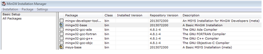
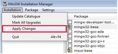
-
Click "Apply Changes" in the "Installation" menu and follow the remaining instructions to complete the installation
-
Add the appropriate item to the Windows operating system Path environment variable. It can be found under Control Panel → System and Security → System → Advanced System Settings in the "Environment Variables..." section. The path is:
<mingw_install_dir>\binNote: Assuming the default installation path,
C:\MinGW, an example is shown below. If the path is not set correctly, the toolchain does not work. If you haveC:\MinGW\msys\x.x\binin yourPATHvariable (as required by KSDK 1.0.0), remove it to ensure that the new GCC build system works correctly. -
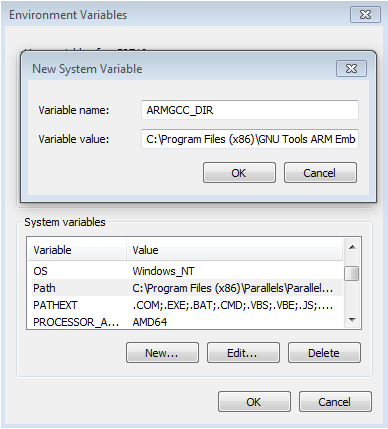
Create a new system environment variable and name it
ArmGCC_DIR. The value of this variable should point to the Arm GCC Embedded Toolchain installation path, which, for this example, is:C:\Program Files (x86)\GNU Tools Arm Embedded\4.8 2014q3Reference the installation folder of the GNU Arm GCC Embedded tools for the exact path name of your installation
Install CMake
-
Download CMake 3.0.x
-
Before installing CMake, ensure that the option "Add CMake to system PATH" is selected. It is up to the user to select whether it is installed into the PATH for all users or just the current user. In this example, the assumption is that it is installed for all users
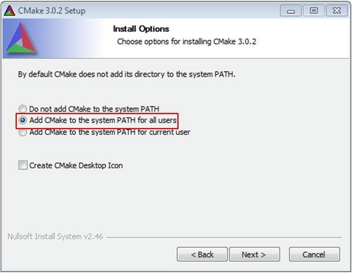
- Follow the remaining instructions of the installer
MCUXpresso SDK
-
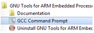
Open a GCC Arm Embedded Toolchain command window. To launch the window, from the Windows Operating System Start menu, go to Programs → GNU Tools Arm Embedded <version> and select GCC Command Prompt
-
Change the directory of the command window to the demo
armgccdirectory and run the build command:<install_dir>\boards\evkmimx8mq\demo_apps\<demo_name>\armgccOr double-click on the
build_all.batfile in Explorer to perform the build. The expected output is shown in this figure: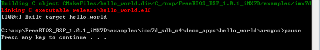
-
There are two project configurations (build targets) supported for each MCUXpresso SDK project:
- Debug: Compiler optimization is set to low, and debug information is generated for the executable. This target should be selected for development and debug
- Release: Compiler optimization is set to high, and debug information is not generated. This target should be selected for final application deployment
Note: There are script files provided to build both configurations. For this example, the
Debugtarget is built andbuild_debug.batis typed on the command line. If theReleasetarget is desired, typebuild_release.batinstead. -
The previous command generates the debug and release binaries (
sdk20-app.bin). These files are in the debug and release folders - Copy the bootable image
sdk20-app.binto the boot partition of the SD card
Run applications using U-Boot
This section describes how to run applications using an SD card and pre-built U-Boot image for i.MX processor.
- Following the steps on the Embedded Linux® tab, prepare an SD card with a pre-built U-Boot and a Linux image from Linux BSP package for the i.MX8MQuad processor. If you have already loaded your SD card with a Linux image you can skip this step
- Insert the SD card to the host computer (Linux or Windows), and copy the application image (for example
sdk20-app.bin) that you want to run to the FAT partition of the SD card - Safely remove the SD card from the PC
- Insert the SD card to the target board. Make sure to use the default boot SD slot and double check the Boot Switch Setup. The default configuration of the validation board boots from
J1601, and on EVK board there is only one SD slot which is used for boot -
Connect the
DEBUG UARTslot on the board with your PC through the USB cable. The Windows OS installs the USB driver automatically, and the Ubuntu OS will find the serial devices as well - Open a second terminal emulator on the i.MX8MQuad EVK board's second enumerated serial port. This is the Cortex-M4's serial console. Set the speed to 115,200 baud rate, 8 data bits, no parity, and power on the board
-
Power up the board and stop the boot process by pressing any key before the U-boot countdown reaches zero. At the U-Boot prompt on the first terminal emulator, type the following commands to U-Boot
=> fatload mmc 1:1 0x7e0000 sdk20-app.bin=> bootaux 0x7e0000
These commands copy the MCUXpressoSDK memory image file from the first partition of the SD card into the Cortex-M4's memory and release the Cortex-M4 from reset
Security and Integrity
Security and Integrity
| Documents and Videos | Description |
|---|---|
| AN12714 i.MX Encrypted Storage Using CAAM Secure Keys | Provides the steps to run a transparent storage encryption at block level using DM-Crypt taking advantage of the secure key feature provided by i.MX's Cryptographic Accelerator and Assurance Module (CAAM). |
| AN12632 Enhanced OpenSSL on i.MX 8M and i.MX 8MM | This application note describes how to add support for accelerated OP-TEE OS with Cryptographic Accelerator and Assurance Module (CAAM) on top of OpenSSL. The final result being an enhanced OpenSSL capable of accelerating crypto algorithms in a secure way via OP-TEE. |
| Trusted Execution Environment: Getting Started with OP-TEE on i.MX Processors | An overview of TEE, example use cases and how to leverage i.MX hardware security features from OP-TEE. |
| AN12838 Strengthening Public Key Cryptography using CAAM Secure Key | Describes the public key cryptography scheme based on the Black Key feature provided by the i.MX application processors. |
| Secure the Edge: Manufacturing Protection: Provision Sensitive Material in an Unsecure Environment | This webinar will provide an introduction to the Manufacturing protection feature and discuss how it can be used to ensure that sensitive material is delivered and installed securely. |
| AN4581 i.MX Secure Boot on HABv4 Supported Devices | This application note provides a secure boot reference for i.MX applications processors that include HABv4 and demonstrates an example for generating signed images and configuring the IC to run securely. |
CAAM Module Example
The i.MX 8M SoC includes the Cryptographic Acceleration and Assurance Module (CAAM) module that can be used through CryptoDev in order to accelerate by hardware the encryption and decryption process. Because the CAAM module is on the SoC, the i.MX8M EVK board supports it as well. It is recommended to use this module when working with large amounts of data or in any application where performance is important.
Checking the speed performance
OpenSSL is an open source project that defines the security protocols SSL (Secure Sockets Layer) and TLS (Transport Layer Security). It has a software library that can be used in applications that require a secure information transmission in order to prevent eavesdropping.
OpenSSL includes a speed command that tests the encryption performance for a desired encryption algorithm. For this example, the algorithm used is the aes-128-cbc that implements the Advanced Encryption Standard (AES) encryption algorithm, with a Cipher Block Chaining (CBC) mode of operation and 128 bits block.
The OpenSSL speed test can be seen using the following command:
#openssl speed -evp aes-128-cbc

Doing aes-128-cbc for 3s on 16 size blocks: 43389139 aes-128-cbc's in 2.99s
Doing aes-128-cbc for 3s on 64 size blocks: 28788614 aes-128-cbc's in 3.00s
Doing aes-128-cbc for 3s on 256 size blocks: 11766741 aes-128-cbc's in 2.99s
Doing aes-128-cbc for 3s on 1024 size blocks: 3674139 aes-128-cbc's in 2.99s
Doing aes-128-cbc for 3s on 8192 size blocks: 495157 aes-128-cbc's in 3.00s

OpenSSL 1.0.2p 14 Aug 2018
built on: reproducible build, date unspecified
options: bn(64,64) rc4(ptr,char) des(idx,cisc,16,int) aes(partial) idea(int) blowfish(ptr)
compiler: arm-poky-linux-gnueabi-gcc -march=armv7ve -mfpu=neon -mfloat-abi=hard -mcpu=cortex-a7 -DL_ENDIAN -DTERMIO -O2 -pipe -g -feliminate-unused-debug-types -Wall -Wa,--noexecstack -DHAVE_CRYPTODEV -DUSE_CRYPTODEV_DIGESTS
The 'numbers' are in 1000s of bytes per second processed.
type 16 bytes 64 bytes 256 bytes 1024 bytes 8192 bytes.
Aes-128-cbc 193627.86k 513839.78k 837089.96k 1048974.64k 1130986.42k
Solution: In the document: "AN12838 Strengthening Public Key Crptography using CAAM Secure Key" section 5.2.1 and 5.2.2. it is described the details of usage.
Tools and References
Wired Communications
Wired Communications
With Linux running on the i.MX board, you can evaluate special features that i.MX SoCs provide. This tutorial shows the step-by-step instructions on how to connect to the Internet on Linux with i.MX 8M EVK:
- Connect an Ethernet cable to the board
RJ-45connector - Boot up the board and wait for the Linux prompt
-
At the Linux prompt, enter the following command
#Log in: root #ifconfig eth0 - Ping any site to corroborate functionality
#ping 8.8.8.8 PING 8.8.8.8 (8.8.8.8) 56(84) bytes of data.

64 bytes from 8.8.8.8: icmp_seq=1 ttl=119 time=4.81 ms 64 bytes
from 8.8.8.8: icmp_seq=2 ttl=119 time=4.87 ms 64 bytes
from 8.8.8.8: icmp_seq=3 ttl=119 time=4.94 ms 64 bytes
from 8.8.8.8: icmp_seq=4 ttl=119 time=4.61 msWireless Connectivity
Wireless Connectivity
| Documents and Videos | Description |
|---|---|
| Cloud Connectivity | Integrated support for cloud services including Amazon Web Services, Microsoft Azure and Google Cloud IoT. |
| Getting Started with NXP-based WiFi modules on i.MX 8M Quad EVK Running Linux OS | This manual covers the bring-up of i.MX 8M Quad EVK, configurations for the BSP image, hardware connection with NXP-based wireless modules and how to bring up the Wi-Fi and Bluetooth interfaces. |
| Feature Configuration Guide for NXP-based Wireless Modules on i.MX 8M Quad EVK | This document specifies the Wi-Fi/Bluetooth features and configurations on i.MX 8M Quad EVK with Azurewave AW-CM358MA (88W8987) and Azurewave AW-CM276MA (88W8997) wireless modules. It covers the initialization and configuration of the Wi-Fi and Bluetooth interfaces. |
Power Management
Power Management
The PF4210 is the NXP 14-Channel Power Management IC Optimized for i.MX 8M.
| Documents and Videos | Description |
|---|---|
| AN12118 i.MX 8M Quad Power Consumption Measurement | Illustrates the current drain measurements of the i.MX 8M Quad application processors taken on the NXP EVK platform through several use cases. |
| AN12225 How to Reduce SoC Power when Running M4 with A53 on i.MX8M | With AMP applications a user may find a VDD_SOC current that is much higher than expected. This document discusses the root cause and solution. |
| M4 Low Power Demo on i.MX 8MM | Allows you to test power consumption on the i.MX 8M EVKs. |
Low Power Mode Suspension Example
With Linux running on the i.MX board, you can evaluate special features that i.MX SoCs provide. This example shows how to suspend to low-power modes and resume to normal operation.
Enter the command below in order to enable serial TTY as a wake up source for the board:
#echo enabled > /sys/class/tty/ttymxc0/power/wakeupEnter the command below to enter Suspend-To-RAM mode:
#echo mem > /sys/power/state

PM: suspend entry (deep)
PM: Syncing filesystems ... done.

Freezing user space processes ... (elapsed 0.001 seconds) done.
OOM killer disabled.
Freezing remaining freezable tasks ... (elapsed 0.000 seconds) done.

Suspending console(s) (use no_console_suspend to debug)
Press the SW1701 switch to wake-up the board. The following messages should appear on terminal:
HIFsuspendwow TODO
PM: suspend devices took 0.112 seconds Disabling non-boot CPUs ...
CPU1: shutdown
psci: CPU1 killed.
CPU2: shutdown
psci: CPU2 killed.
CPU3: shutdown
psci: Retrying again to check for CPU kill
psci: CPU3 killed.
Enabling non-boot CPUs ...
Detected VIPT I-cache on CPU1
GICv3: CPU1: found redistributor 1 region 0:0x00000000388a0000
CPU1: Booted secondary processor [410fd034]
cache: parent cpu1 should not be sleeping CPU1 is up Detected VIPT I-cache on CPU2
GICv3: CPU2: found redistributor 2 region 0:0x00000000388c0000
CPU2: Booted secondary processor [410fd034]
cache: parent cpu2 should not be sleeping CPU2 is up Detected VIPT I-cache on CPU3
GICv3: CPU3: found redistributor 3 region 0:0x00000000388e0000
CPU3: Booted secondary processor [410fd034]
cache: parent cpu3 should not be sleeping
CPU3 is up
PM: resume devices took 0.028 seconds
OOM killer enabled.
Restarting tasks ... done.
PM: suspend exitAudio
Audio
| Documents and Videos | Description |
|---|---|
| DSP Concepts offering for i.MX 8 Processors | Learn about audio platform offerings from DSP Concepts for the i.MX 8M family. |
| AN12195 Implement Low-Power Audio on i.MX8M | This document discusses low power audio application design on the i.MX 8M. |
Simple Audio Example
This simple example shows the link between audiotestsrc and alsasink.
Connect your earphone to the Audio Jack on the i.MX 8M EVK board.
If your earphone includes a microphone feature (TRRS with four contacts), do not push the microphone jack to the end. Leave one contact ring outside.
#aplay -1

**** List of PLAYBACK Hardware Devices ****
card 0: imxspdif [imx-spdif], device 0: S/PDIF PCM snd-soc-dummy-dai-0 [S/PDIF PCM snd-soc-dummy-dai-0]
Subdevices: 1/1
Subdevice #0: subdevice #0
card 2: wm8524audio [wm8524-audio], device 0: HiFi wm8524-hifi-0
[]
Subdevices: 1/1
Subdevice #0: subdevice #0
card 2: wm8524audio [wm8524-audio], device 1: HiFi-ASRC-FE (*)
[]
Subdevices: 1/1
Subdevice #0: subdevice #0

# gst-launch-1.0 audiotestsrc ! alsasink device=plughw:2

Setting pipeline to PAUSED ...
Pipeline is PREROLLING ...
Redistribute latency...
Pipeline is PREROLLED ...
Setting pipeline to PLAYING ...

New clock: GetAudioSinkClock
You should be able to listen to a tone on the earphone.
When you are done with the tone, finish the command line by pressing Ctrl+C.
Decoder Video Audio Example
This example explains how to decode just the audio from a video file. Copy a video file to your /home/root/ on your SD card rootfs partition, boot the board from the SD card and run the command below:
#gplay-1.0 SampleVideo_1280x720_2mb.mp4

FSL_GPLAY2_01.00_LINUX build on Mar 12 2018 11:48:19

Set VideoSink kmssink
Set TextSink fakesink ====== AIUR: 4.3.4 build on Mar 12 2018 11:47:35. ======
Core: AVI_PARSER_03.05.29 build on Aug 31 2017 09:15:57

file: /usr/lib/imx-mm/parser/lib_avi_parser_arm_elinux.so.3.1

Track 00 [video]: Disabled

Codec: 4, SubCodec: 1

------------------------
------------------------ Track 01 [audio_0] Enabled

Duration: 0:09:56.424000000
Language: und
Mime: audio/mpeg, mpegversion=(int)1, channels=(int)2, rate=(int)48000, bitrate=(int)0
codec_data=(buffer)014d401fffe10017674d401fda014016ec0440000003004000000c83c60ca801000468ef3c80

------------------------

====== BEEP: 4.3.4 build on Mar 12 2018 11:47:45. ======

Core: MP3 decoder Wrapper build on Jan 11 2018 10:20:25

file: /usr/lib/imx-mm/audio-codec/wrap/lib_mp3d_wrap_arm_elinux.so.3

CODEC: BLN_MAD-MMCODECS_MP3D_ARM_02.13.01_ARMV8 build on Jan 11 2018 10:05:45. [Stop (No Repeated)][Vol=1.0][00:00:00/00:09:56]

=========== fsl_player_play()===========

FSL_GPLAY2_01.00_LINUX build on Mar 12 2018 11:48:19

[h]display the operation Help
[p]Play
[s]Stop
[e]Seek
[a]Pause when playing, play when paused
[v]Volume
[m]Switch to mute or not
[>]Play next file
[r]Switch to repeated mode or not
[u]Select the video track
[d]Select the audio track
[b]Select the subtitle track
[f]Set full screen
[z]resize the width and height
[t]Rotate
[c]Setting play rate
[i]Display the metadata
[x]exit

State changed: buffering
State changed: playing

[Playing (No Repeated)][Vol =1.0][00:00:13/00:00:13]EOS Found

getNextItem No next item!
No more media file, exit gplay!

State changed: stopped

Exit display thread

FSL_PLAYER_UI_MSG_EXIT

fsl_player_deinitDisplay and Graphics
Display and Graphics
| Documents and Videos | Description |
|---|---|
| i.MX Graphics User’s Guide | Provides information on graphic APIs and driver support for developers writing graphics applications or video drivers. |
| i.MX 8 GStreamer User Guide | Learn more about how to use GStreamer version 1.0 on the i.MX 8M EVK. Includes examples for decode, encode, camera, video composition and video scaling and rotation. |
| Implementing Graphics in Real-time Industrial HMI Systems with NXP MCUs and Embedded Wizard | NXP has partnered with TARA Systems to offer Embedded Wizard as an Enabling Software Technology. |
| AN12189 Quick Start Guide for i.MX8-DSI-OLED1 for i.MX 8M Evaluation Kit | Provides an overview of the i.MX 8M and how Crank Software’s Storyboard differs from traditional UI development tools. |
| AN12188 Quick Start Guide for IMX-MIPI-HDMI for i.MX 8M Evaluation Kit | This document provides a brief overview on how to get started with the i.MX 8M EVK and the IMX-MIPI-HDMI accessory card, which is used for converting the MIPI-DSI signal to an HDMI signal. |
| AN12187 Quick Start Guide for MINISASTOCSI for i.MX 8M Evaluation Kit | This document provides a brief overview on how to get started with the i.MX 8M EVK and the MINISASTOCSI accessory card, a MIPI-CSI interface camera kit based on OmniVision chipset OV5640. |
Camera Interfaces
Camera Interfaces
| Documents and Videos | Description |
|---|---|
| i.MX 8 Camera Use Cases | Learn more about the i.MX 8 MIPI CSI use case, Advanced GStreamer camera use cases, available cameras and daughter cards supported by the i.MX 8M EVKB, compatible Device Tree (DTS) files, and how to enable different camera options. |
| i.MX 8 GStreamer User Guide | Learn more about how to use GStreamer version 1.0 on the i.MX 8M EVK. Includes examples for decode, encode, camera, video composition and video scaling and rotation. |
| AN12187 Quick Start Guide for MINISASTOCSI for i.MX 8M Evaluation Kit | This document provides a brief overview on how to get started with the i.MX 8M EVK and the MINISASTOCSI accessory card, a MIPI-CSI interface camera kit based on OmniVision chipset OV5640. |
Machine Learning
Machine Learning
Machine learning (ML) typically encompasses applications where classification, recognition and prediction of man-made abstractions are desired. Examples include Image Recognition, Gesture Recognition, Anomaly Detection, Speech-to-Text, Text-to-Speech, ASR, Scene Recognition and many more. This section will focus specifically on the NXP ML tools applied to image or video streams. The audio section may reference the included examples.
| Documents and Videos | Description |
|---|---|
| eIQ® ML Software Development Environment | Enables the use of ML algorithms on NXP MCUs, i.MX RT crossover MCUs, and i.MX family SoCs. eIQ software includes inference engines, neural network compilers and optimized libraries. |
| i.MX Machine Learning User’s Guide | The NXP eIQ UM for i.MX toolkit provides a set of libraries and development tools for machine learning applications targeting NXP microcontrollers and application processors. |
| NXP eIQ Machine Learning Software Development Environment for i.MX Applications Processors | This document provides guidance for the supported ML software for the i.MX family and includes an eIQ Introduction, Yocto Installation Guide and step-by step guide for running all supported DNN and non-DNN examples. |
| eIQ FAQ | This document covers some of the most commonly asked questions we've gotten about eIQ and embedded machine learning. |
| AN13001 Glow Memory Analysis | How to understand the Glow memory information generated by the Glow compiler and calculate the memory required for a particular model. This compiler can then be used to determine the minimum memory size that is needed to run the model. |
| AN12766 Anomaly Detection with eIQ using K-Means clustering in Tensor Flow Lite | Step by step instructions to enable a machine condition monitoring application using anomaly detection. |
| Getting Started with eIQ Software for i.MX Applications Processors | A series of step-by-step tutorials using our eIQ ML software development environment from unboxing a board, to deploying, modeling and inferencing at the edge. |
Device Management and Secure OTA
Device Management and Secure OTA
| Documents and Videos | Description |
|---|---|
| AN12900 Secure Over-the-Air Prototype for Linux Using CAAM and Mender or SW Update | Provides a prototype implementation for Secure OTA for Linux images, specifically for the i.MX 8M/MM. |
| AN12921 Google Cast Authentication Aspects Implementation on i.MX | This application note provides details about security properties required for Google Voice Assistant (GVA) and Cast for Audio (C4A) on the security aspects and their implementations on NXP’s GVA/C4A reference platform. |
| Docker On i.MX8MM with Ubuntu | This document describes a way to create Ubuntu rootfson host PC and install docker for any ARM 64 platform. |
Minicom Tutorial
Serial Communication Console Setup
On the command prompt of the Linux host machine, run the following command to determine the port number:
$ls /dev/ttyUSB* The smaller number is for Arm® Cortex®-A53 core and the bigger number is for Arm® Cortex®-M4 core.
Minicom
Use the following commands to install and run the serial communication program (minicom as an example):
- Install Minicom using Ubuntu package manager
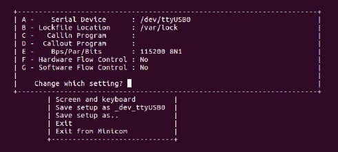
$sudo apt-get install minicom - Launch Minicom using a console window using the port number determined earlier
$sudo minicom /dev/ttyUSB* -s -
Configure Minicom as shown in Figure 12
- The next step is to Connect the HDMI cable
Tera Term Tutorial
Serial Communication Console Setup
The FTDI USB-serial chip on i.MX8MQuad enumerates two serial ports. Assume that the ports are COM9 and COM10. The smaller numbered port ( COM9) is for the serial console communication from Arm® Cortex®-A53 and the larger numbered port (COM10) is for Arm® Cortex®-M4 core. The serial-to-USB drivers are available at FTDI Chip Drivers .
Tera Term Tutorial
Tera Term is an open source terminal emulation application. This program displays the information sent from the NXP development platform's virtual serial port.
- Download Tera Term . After the download, run the installer and then return to this webpage to continue
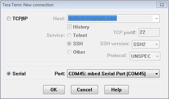
- Launch TeraTerm. The first time it launches, it shows the following dialog. Select the Serial option. Assuming your board is plugged in, there should be a COM port automatically populated in the list
- Configure the serial port settings (using the COM port number identified earlier) to 115,200 baud rate, 8 data bits, no parity and 1 stop bit. To do this, go to Setup → Serial Port and change the settings
- Verify that the connection is open. If connected, Tera Term shows something like below in its title bar
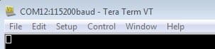
- The next step is to Connect the HDMI cable
PuTTY Tutorial
Serial Communication Console Setup
The FTDI USB-serial chip on i.MX8MQuad enumerates two serial ports. Assume that the ports are COM9 and COM10. The smaller numbered port (COM9) is for the serial console communication from Arm® Cortex®-A53 and the larger numbered port (COM10) is for Arm® Cortex®-M4. The serial-to-USB drivers are available at FTD Chip Drivers .
PuTTY Tutorial
PuTTY is a popular terminal-emulation application. This program displays the information sent from the NXP development platform's virtual serial port.
- Download PuTTY . After the download, run the installer and then return to this webpage to continue
- Launch PuTTY by either double clicking on the executable file you downloaded or from the Start menu, depending on the type of download you selected
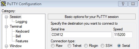
- Configure in the window that launches. Select the Serial radio button and enter the COM port number that you determined earlier. Also, enter the baud rate, in this case 115,200
- Click open to open the serial connection. Assuming that the board is connected and you entered the correct COM port, the terminal window will open. If the configuration is not correct, PuTTY will alert you
- The next step is to Connect the HDMI cable
Design Resources
Board Information
Chip Documents
- i.MX 8MDQLQ Hardware Developer’s Guide
- IMX8MDQLQ_0N14W Mask Set Errata for Mask 0N14W
- i.MX 8M Dual/8M QuadLite/8M Quad Applications Processor Reference Manual
- i.MX 8M Dual/8M QuadLite/8M Quad Applications Processor Datasheet for Industrial Products
- i.MX 8M Dual/8M QuadLite/8M Quad Applications Processor Datasheet for Consumer Products
Software
i.MX8MQuad EVK Linux BSP Documents
- i.MX BSP Porting Guide
- i.MX Linux User’s Guide
- i.MX Linux Release Notes
- L4.9.88_2.0.0 Document Bundle
- i.MX Linux Reference Manual
- i.MX Graphics Users Guide Linux
- i.MX Yocto Project Users Guide Linux
- i.MX VPU API Linux Reference Manual
- i.MX Yocto Project: Frequently Asked Questions
i.MX8MQuad EVK Android BSP Documents
Support
Trainings
To learn what to do next, find your issue below. If you still need help, contact NXP Support.
| Trainings | Description |
|---|---|
| i.MX 8M Training | Full list of on-demand training, how-to videos and webinars from NXP about this product. |
Forums
Connect with other engineers and get expert advice on designing with the i.MX 8M on one of our community sites.
Product Forums:
- i.MX Forums
- i.MX Graphics
- i.MX Solutions
- Power Management
- Wireless Connectivity
- i.MX8 Coral Development Kit
- Useful Documents and Threads of i.MX Processors