Getting Started with the MIMXRT595-EVK
Contents of this document
-
Plug it In
-
Get Software
-
Build, Run
-
Modify a SDK Example
Sign in to save your progress. Don't have an account? Create one.
Purchase your RT595 Evaluation Kit
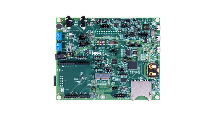
1. Plug it In
Let's take your MIMXRT595-EVK for a test drive! You have the choice of watching the sequence in a short video or following the detailed actions listed below.
1.2 Attach the USB Cable
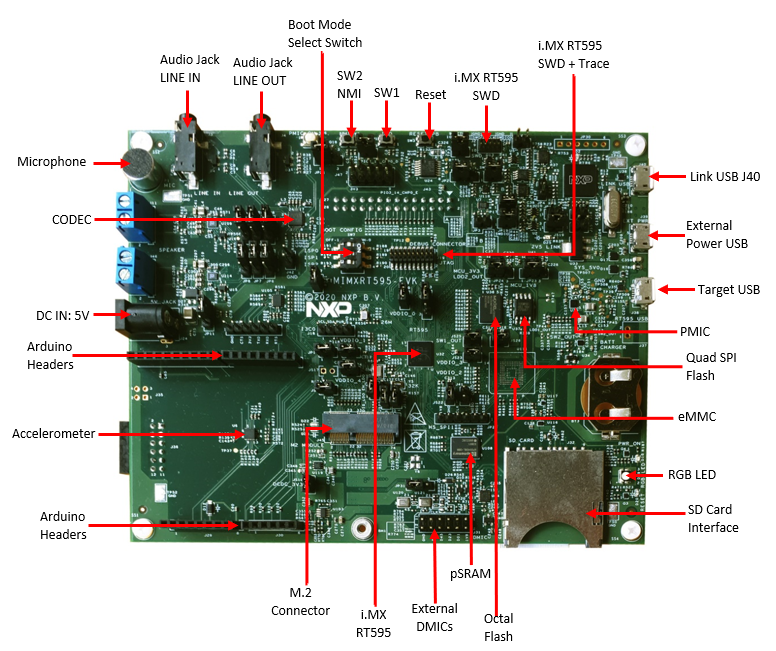
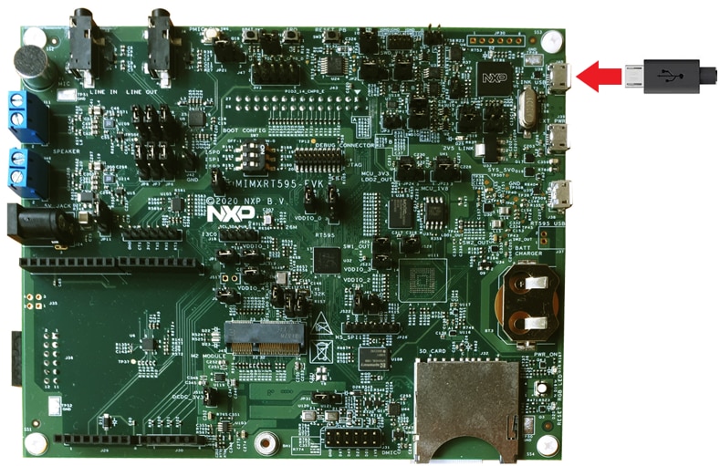
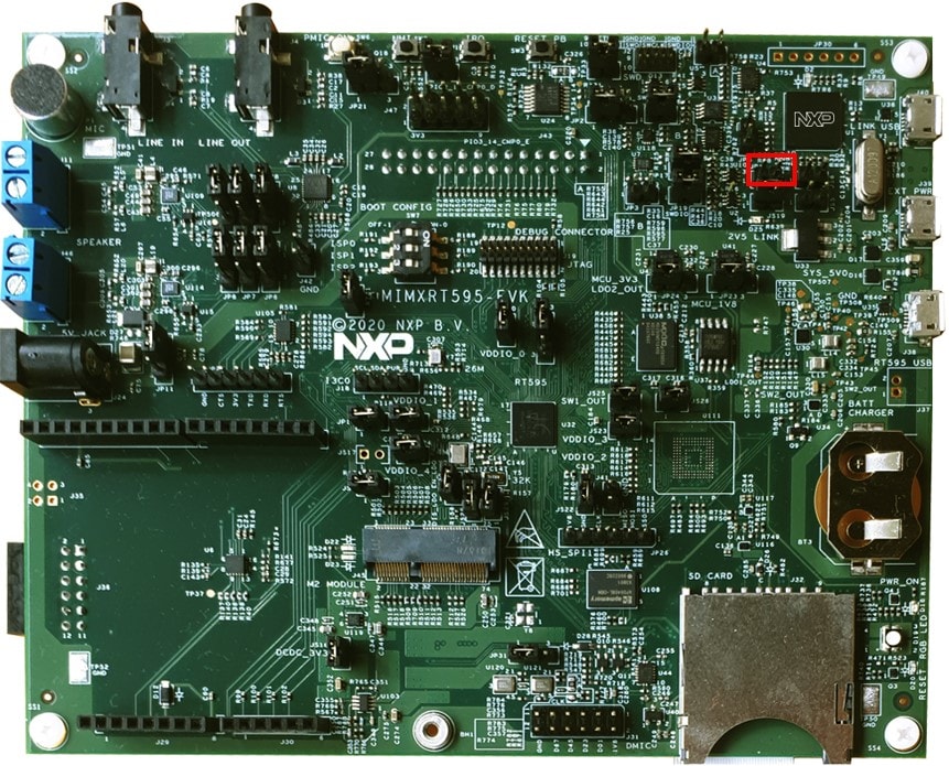
There are three micro-USB connectors on the board. Plug the USB cable into the one labeled Link USB (J40), as is shown in the photo below.
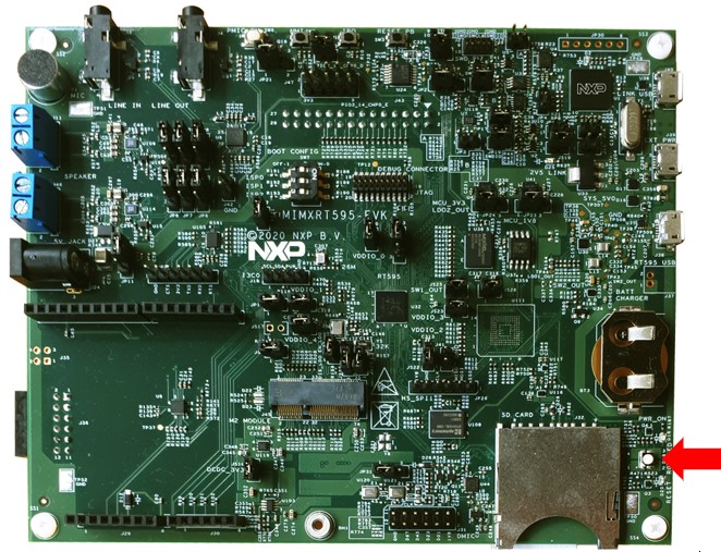
When the board is powered, the RGB LED D19 should flash on and off.

1.3 Run the Out-of-Box Demo
Your MIMXRT595-EVK comes loaded with a "LED blinky" demo, explained below, and a demo that exercises the Cortex M33, Fusion F1 DSP and the GPU. This out of the box demo will be shown in an Application Note.
When the board is powered, the RGB LED D19 should flash on and off.
2. Get Software
2.1 Jump Start Your Design with the MCUXpresso SDK
The MCUXpresso Software Development Kit (SDK) is complimentary and includes full source code under a permissive open-source license for all hardware abstraction and peripheral driver software.
Click below to download a pre-configured SDK release for the MIMXRT595-EVK. Unzip the SDK into a directory path that does not contain any spaces.

You can also use the online SDK Builder to create a custom SDK package for the MIMXRT595-EVK.
2.2 Install Your Toolchain
The MCUXpresso Software Development Kit (SDK) is complimentary and includes full source code under a permissive open-source license for all hardware abstraction and peripheral driver software.
Click below to download a pre-configured SDK release for the MIMXRT595-EVK. Unzip the SDK into a directory path that does not contain any spaces.
You can also use the online SDK Builder to create a custom SDK package for the MIMXRT595-EVK.
NXP offers a complimentary toolchain called MCUXpresso IDE. Please download MCUXpresso v11.3.0 or above.

Want to use a different toolchain?
The MCUXpresso SDK includes support for other tools such as IAR , Keil and command-line GCC .

2.3 MCUXpresso Config Tools
The MCUXpresso Config Tool is an integrated suite of configuration tools that guides users in creating new MCUXpresso SDK projects, and also provides pin and clock tools to generate initialization C code for custom board support, It is fully integrated as a part of MCUXpresso IDE, or you can download it as a seperate tool if using different toolchain. MCUXpresso Config Tool v9.0 or above is needed to support the i.MXRT595.

2.4 LPCScrypt
Drivers for the debugger and virtual COM port also need to be installed. They are part of the LPCScrypt package, which can be download below. The LPC-Link2 circuiit firmaware will also need to be updated to use the J-Link interface. The tutorial below will walk through the steps.
2.5 Serial Terminal
Many of the MCUXpresso SDK examples applications output data over the MCU UART. Install and configure your preferred terminal software to 115200 baud rate, 8 data bits, no parity and 1 stop bit. To determine the port number of the MIMXRT595-EVK's virtual COM port, open the device manager and look under the "Ports (COM and LPT)" group.
Not sure how to use a terminal application? Try one of these tutorials:
MCUXpresso Terminal, Tera Term Tutorial, PuTTY Tutorial2.6 J-Link
You will need to download the neccessary J-Link drivers in order to debug the Fusion F1 DSP. Follow the next tutorial to see how to download and install this software.
2.7 Install Xtensa Xplorer IDE and Tools
To code and debug the DSP on the MIMXRT595-EVK, you will need to download Cadence Tensilica Xplorer. This is the only available development IDE for the DSP core of the MIMXRT595
3. Build, Run
3.1 Explore the MCUXpresso SDK Example Code
The MCUXpresso SDK comes with a long list of example applications code. To see what's available, browse to the SDK boards folder of your SDK installation and select MIMXRT595-EVK. (<SDK_Install_Directory>/boards/evkmimxrt595).
To learn more about specific example code, open the readme.txt file in an example's directory.
3.2 Building and Debugging MCUXpresso SDK Examples
If one or more of the demo application or driver examples sounds interesting, you're probably wanting to know how you can build and debug yourself. The Getting Started with SDK guide provides easy, step-by-step instructions on how to configure, build, and debug demos for all toolchains supported by the SDK. Use the guide below to learn how to open, build and debug an example application in MCUXpresso IDE.
Use MCUXpresso IDE
Building and running a DSP demo
The RT500 SDK provides a collection of DSP example applications. Each DSP example has two source directories, one for the ARM CM33 and one for the DSP Fusion F1.
In order to debug a DSP demo you will need to follow two processes. The first one is to build and flash the CM33 application to your MIMXRT595-EVK. The second one is to build and debug the DSP application using Xtensa Xplorer IDE.
Build and Flash Cortex-M33 Application
The following steps will guide you through the mu_polling application using MCUXpresso IDE for the Cortex-M33 application. The MCUXpresso IDE installation can be found at the section “2. Get Software” of this Getting Started guide.
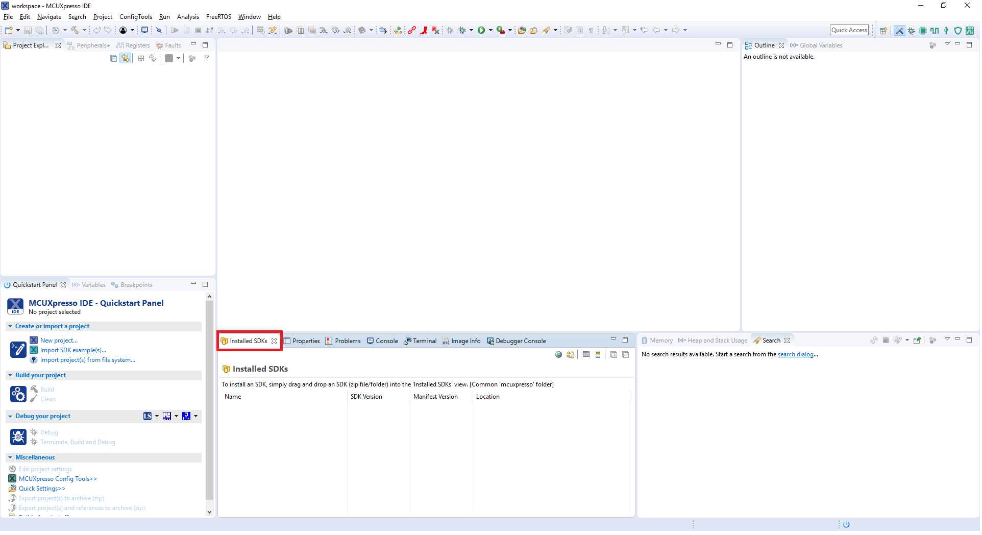
- Open the MCUXpresso IDE.
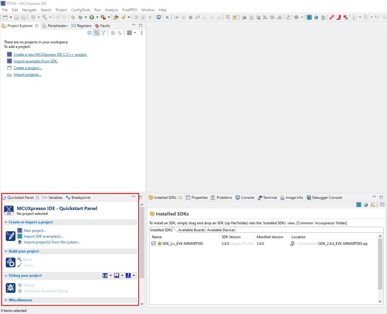
- Switch to the Installed SDKs view within the MCUXpresso IDE window.
- Drag and drop the MIMXRT595-EVK SDK (zipped) file into the Installed SDKs view.
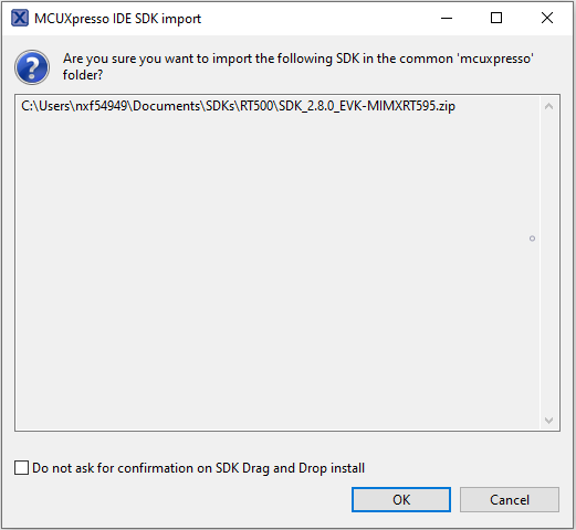
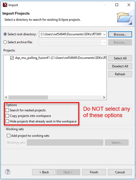
- You will get the following pop-up. Click on OK to continue the import:
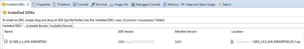
- The installed SDK will appear in the Installed SDKs view as shown below:
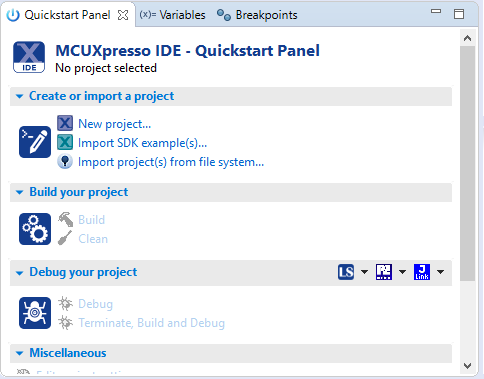
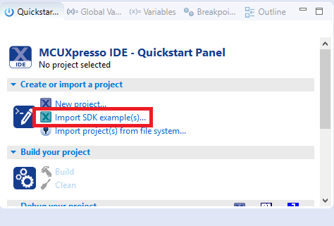
- Find the Quickstart Panel in the lower left-hand corner.
- Then click on Import SDK example(s)…
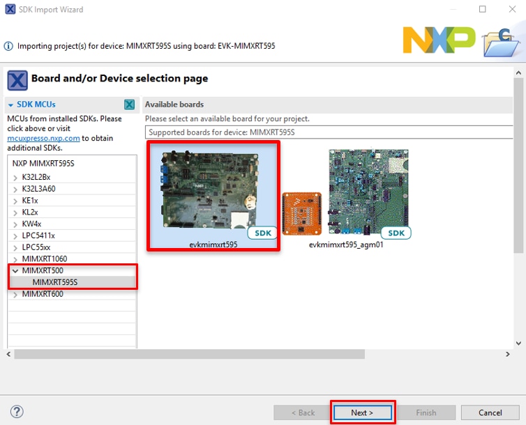
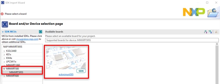
- Click on the evkmimxrt595 board to select that you want to import an example that can run on that board, and then click on Next.
-
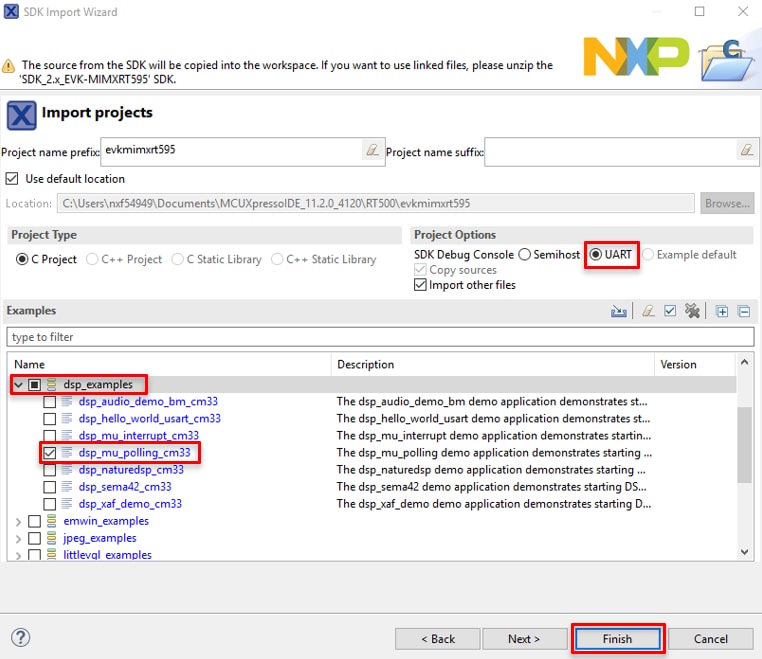
Use the arrow button to expand the
dsp_examplescategory, and then click the checkbox next todsp_mu_polling_cm33to select that project. To use the UART for printing (instead of the default semihosting), select UART as the SDK Debug Console checkbox under the project options. Then, click on Finish. - Verify the
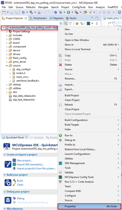
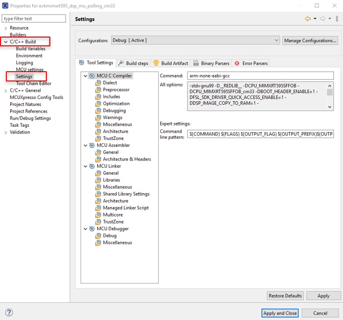
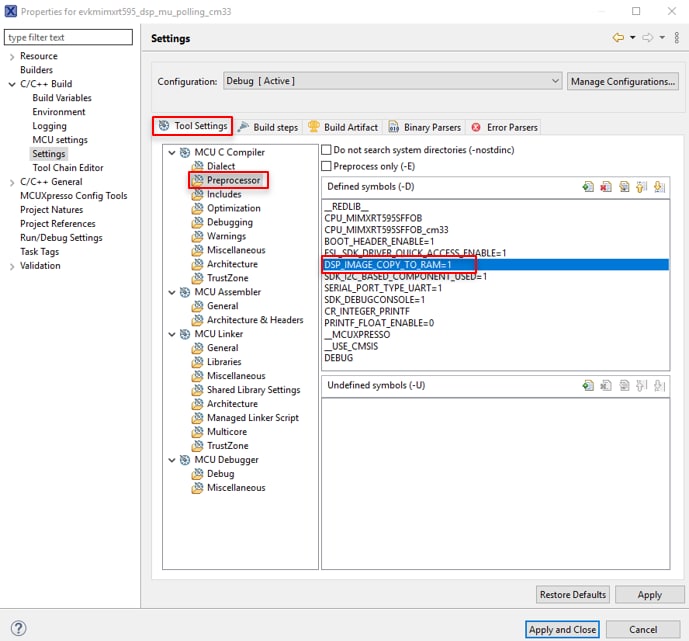
DSP_IMAGE_COPY_TO_RAMmacro value. To do this, go to project properties doing right click on the project. - Open C/C++ Build option and select Settings.
-
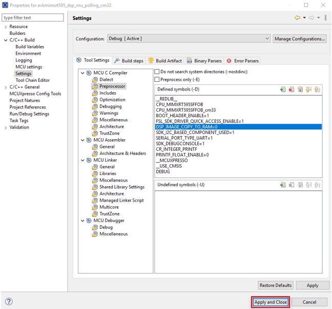
Once in there, into the Tool Settings, select the Preprocessor folder and change the value of
DSP_COPY_IMAGE_TO_RAM to 0. - Apply and Close.
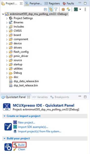
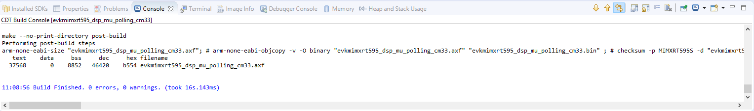
- Select the project and build it.
- The project will build without problems.
- Connect the board to your computer with the micro USB to J40 'LINK USB' port.
- Download the application to your MIMXRT595-EVK.
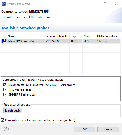
- Select the J-Link debug probe.
- Run the application.

Build and Debug the DSP application
The following steps will guide you through the mu_polling application using Xtensa Xplorer IDE for the DSP. The Xtensa Xplorer IDE installation can be found at the section “2. Get Software” of this Getting Started guide.
- Open Xtensa Xplorer IDE.
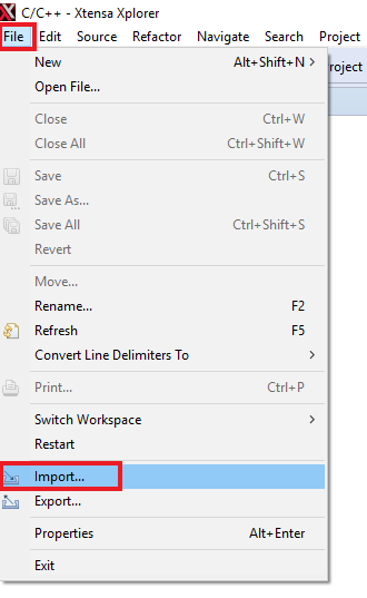
- Import the “mu_polling” demo on your workspace. File → Import
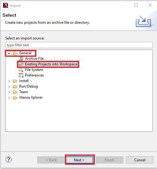
- Select Existing Projects into Workspace.
-
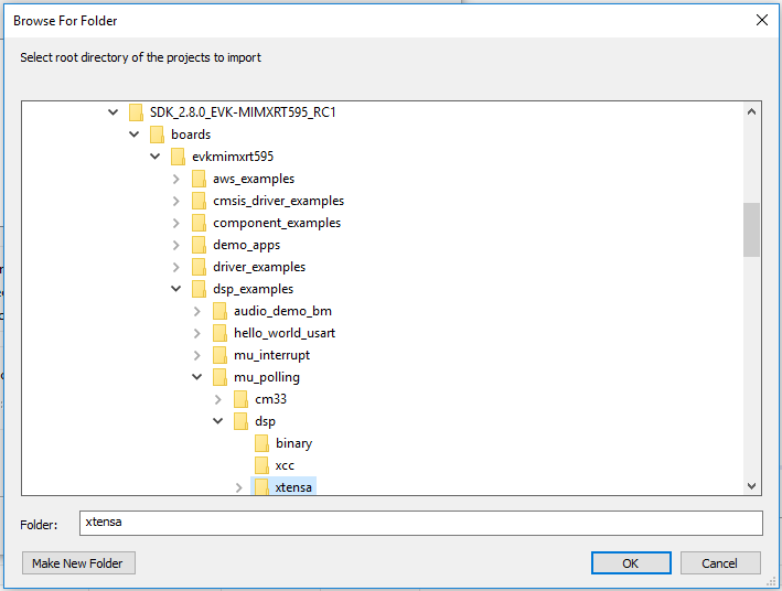
Use the Browse button and select the mu_polling dsp demo on the SDK. Make sure the path name does not contain any spaces.
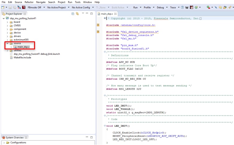
The path is:“<SDK install dir> \boards\evkmimxrt595\dsp_examples\mu_polling\dsp” - Once imported, you will see '
dsp_mu_polling_fusionf1' in the Project Explorer. This project includes the code for the DSP. You can see the main function at source →main_dsp.c. - To build the DSP application you must set the following configuration (use the drop down buttons on the menu bar):

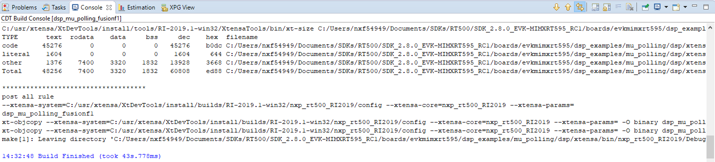
- Build the application by doing click on the “Build Active” button
- The build should complete without errors. If there are errors, verify that the SDK directory path does not contain any spaces.
-
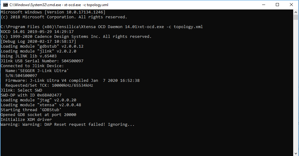
Open a command prompt on the following location:
“C:\Program Files (x86)\Tensilica\Xtensa OCD Daemon 14.01”and execute the following command: “xt-ocd.exe -c topology.xml”. You should see the following: -
Open the terminal application on the PC (such as PuTTY or Tera Term) and connect to the debug COM port you determined earlier. Configure the terminal with these settings:
- 115200 baud rate
- No parity
- 8 data bits
- 1 stop bit
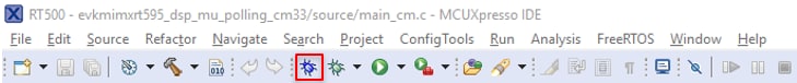
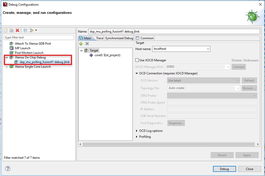
- Go to Xtensa Xplorer IDE and use the Debug action button to open the Debug Configuration.
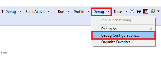
- Please select the dsp_mu_polling Xtensa On Chip Debug. And Click on Debug.
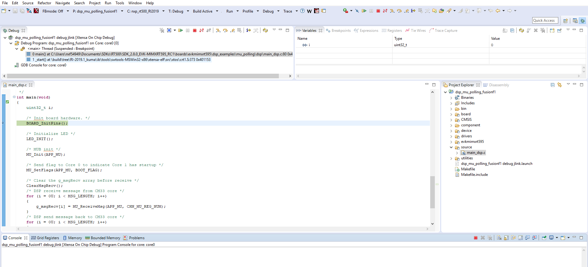
- A new window will be opened asking to download the application to the core 0. Click Yes.

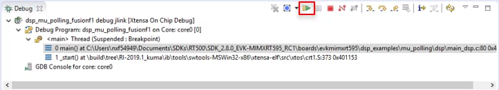
- Xtensa Xplorer will transition to the Debug perspective.
- Click on 'Resume' button to start the program.
- You should see the RED RGB LED D19 blinking and the following on the terminal:
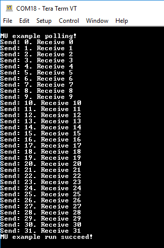
- Click on 'Terminate' button to stop the debugging session on Xtensa Xplorer IDE.
- Stop the debugger on the MCUXpresso IDE running the CM33 application.
Use IAR Ewarm
Build an Example Application
The following steps will guide you through opening the mu_polling application. This application consists of code for both the Cortex M33 and the DSP core. The instructions for compiling and debugging the Cortex M33 core are covered in the instructions below.
Instructions for compiling and debugging the DSP code can be found in Section 2 of the “Use MCUXpresso IDE” tutorial. These steps may change slightly for other example applications as some of these applications may have additional layers of folders in their path.
Please use IAR Embedded Workbench for Arm version 8.50.9 or above.
- First, unzip the previously downloaded RT500 SDK package.
-
Open the desired example application workspace. Most example application workspace files can be located using the following path:
<install_dir>/boards/<sdk_board_name>/<example_type>/<application_name>/iarUsing the mu_polling demo as an example, the path is:
<install_dir>/boards/evkmimxrt595/dsp_examples/mu_polling/cm33/iar - Select the desired build target from the drop-down. For this example, select the “
dsp_mu_polling_cm33 - debug” target.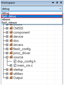
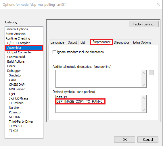
- Change
DSP_IMAGE_COPY_TO_RAMmacro value to 0. Open the project properties by doing a right-click on the project and selecting Options.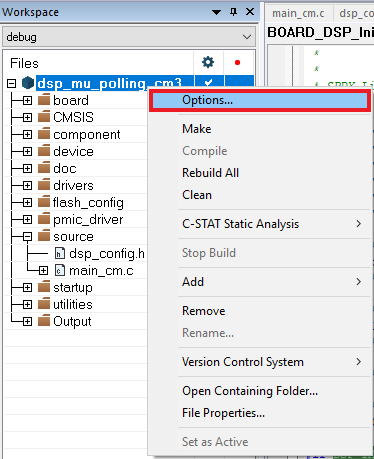
- Click on C/C++ Compiler and select Preprocessor. Change the
DSP_IMAGE_COPY_TO_RAMto 0. - Now go to Assembler, select the Preprocessor option, and change the same macro.
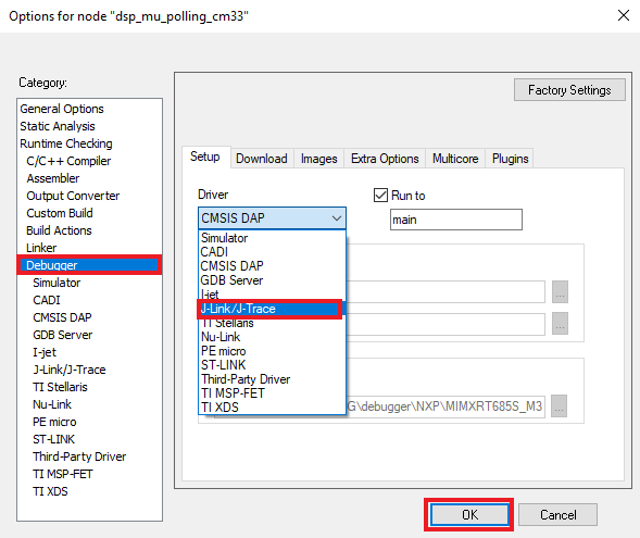
- Now go to the Debugger section and change the debugger driver to Jlink. Press the OK button.
- To build the application, click the “Make” button, highlighted in red below.
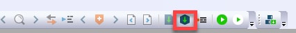 >
> -
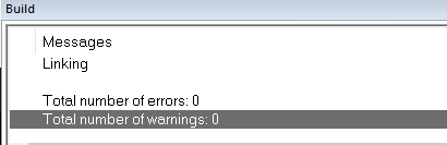
The build will complete without errors.
Run an Example Application
The LPC-Link2 circuit on the board should have been updated to use the J-Link interface during Step 2.4 “LPCScrypt” of the Getting Started website. See that section of the Getting Started website for more details on using LPCScrypt to update the debug firmware on the board to use the J-Link interface if this has not already been done.
-
- Connect the development platform to your PC via USB cable to J40 “Link USB”. Ensure the DFULink jumper (
JP1) is removed when powering the board. - Click the "Download and Debug" button to download the application to the target.

- The application is then downloaded to the target and automatically runs to the main() function.
- Run the code by clicking the "Go" button to start the application.

- The
mu_polling_cm33application is now running on the Cortex-M33.
- Connect the development platform to your PC via USB cable to J40 “Link USB”. Ensure the DFULink jumper (
-
Build and Debug the DSP Application
To build and debug the code for the DSP part of this application, open the “Use MCUXpresso IDE” tutorial and follow the instructions starting at “2. Build and Debug the DSP Application”.
Use ARM GCC
Set Up Toolchain
This section contains the steps to install the necessary components required to build and run a KSDK demo application with the ARM GCC toolchain, as supported by the MCUXpresso SDK. There are many ways to use ARM GCC tools, but this example focuses on a Windows environment. Though not discussed here, GCC tools can also be used with both Linux OS and Mac OSX.
Please use GCC ARM Embedded version 9-2020-q2.
Install GNU-RM ARM Embedded Toolchain
Download and run the installer from: GNU Arm Embedded Toolchain Downloads . This is the GNU Arm Embedded Toolchain (i.e., compiler, linker, etc.) which includes the GNU compiler (GCC).
Install MinGW
The Minimalist GNU for Windows (MinGW) development tools provide a set of tools that are not dependent on third party C-Runtime DLLs (such as Cygwin). The build environment used by the KSDK does not utilize the MinGW build tools, but does leverage the base install of both MinGW and MSYS. MSYS provides a basic shell with a Unix-like interface and tools.
- Download the latest MinGW mingw-get-setup installer from MinGW - Minimalist GNU for Windows Files .
- Run the installer. The recommended installation path is C:\MinGW, however, you may install to any location.
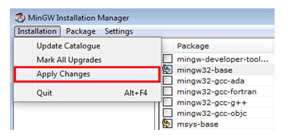
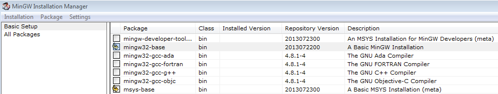
- Ensure that the "
mingw32-base" and "msys-base" are selected under Basic Setup. - Click "Apply Changes" in the "Installation" menu and follow the remaining instructions to complete the installation.
-
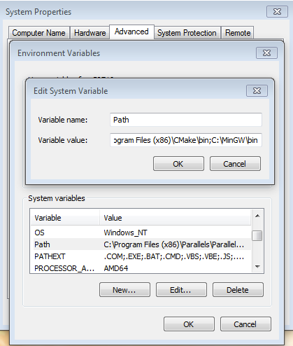
Add the appropriate item to the Windows operating system Path environment variable. It can be found under Control Panel → System → Advanced System Settings in the "Environment Variables..." section. The path is:
<mingw_install_dir>\binAssuming the default installation path,
C:\MinGW, an example is shown below. If the path is not set correctly, the toolchain does not work.
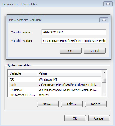
Add a New Environment Variable for ARMGCC_DIR
Create a new system environment variable and name it ARMGCC_DIR. The value of this variable should point to the ARM GCC Embedded tool chain installation path, which, for this example, is:
C:\Program Files (x86)\GNU Tools ARM Embedded\<version>
Reference the installation folder of the GNU ARM GCC Embedded tools for the exact path name of your installation.
Install CMake
- Download the newest version of CMake from: CMake.
- Install CMake, ensuring that the option "Add CMake to system PATH" is selected when installing. It's up to the user to select whether it's installed into the PATH for all users or just the current user. In this example, the assumption is that it's installed for all users.
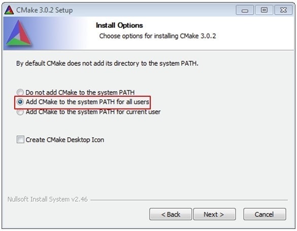
- Follow the remaining instructions of the installer.
- You may need to reboot your system for the PATH changes to take effect.
Build an Example Application
To build an example application, follow these steps.
-
Open the next directory on the file explorer '<SDK Install dir>
\boards\evkmimxrt595\dsp_examples\mu_polling\cm33\armgcc' and open flags.cmake file.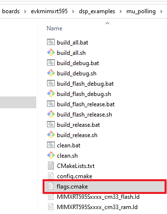
-
Edit the next sections, changing the value of
DDSP_IMAGE_COPY_TO_RAMto 0:CMAKE_ASM_FLAGS_DEBUG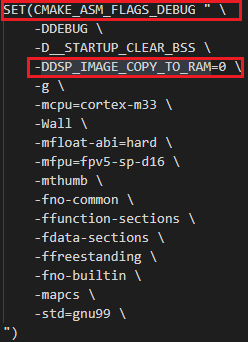
CMAKE_C_FLAGS_DEBUG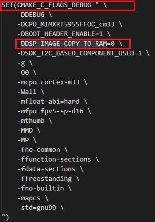
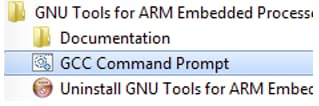
- If not already running, open a GCC ARM Embedded tool chain command window. To launch the window, from the Windows operating system Start menu, go to “Programs → GNU Tools ARM Embedded <version>” and select “GCC Command Prompt”.
-
Change the directory to the example application project directory, which has a path like this:
<install_dir>/boards/<board_name>/<example_type>/<application_name>/armgccFor this guide, the exact path is:
<install_dir>/boards/evkmimxrt685/dsp_examples/mu_polling/cm33/armgcc -
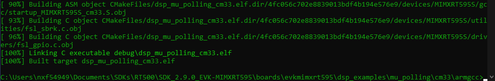
Type “
build_debug.bat” on the command line or double click on the "build_debug.bat" file in Windows operating system Explorer to perform the build. The output is shown in this figure:When finished, a
.elfwill be created inside a folder named 'debug' on the project directory.
Run an Example Application
The GCC tools require a J-Link debug interface. To update the OpenSDA firmware on your board to the latest J-Link app, visit OpenSDA. After installing the J-Link OpenSDA application, download the J-Link driver and software package from: Segger.
-
Connect the development platform to your PC via USB cable to
J40“Link USB”. Ensure the DFULink jumper (JP1) is removed when powering the board. -
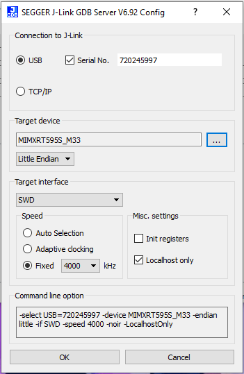
Open the J-Link GDB Server application. Assuming the J-Link software is installed, the application can be launched by
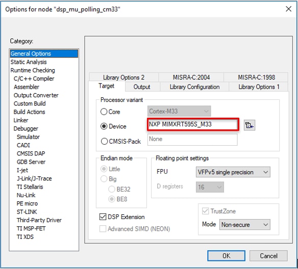
"C:\Program Files (x86)\SEGGER\ J-Link <version> \ J-Link GDB Server". -
Modify the target device selection chosen for this example to “MIMXRT595S_M33” and use the SWD interface.
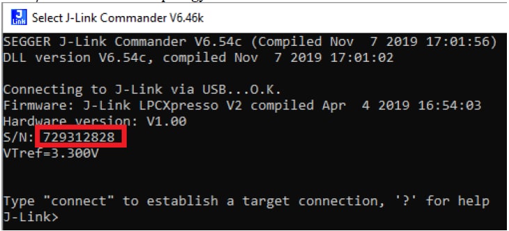
*Your device serial number may be different. You can obtain the device serial number, by opening
Jlink.exe(with your MIMXRT595 already connected throughJ40).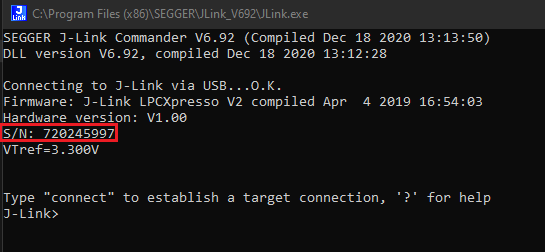
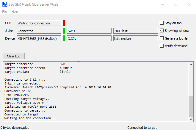
- After it is connected, the screen should resemble this figure:
- If not already running, open a GCC ARM Embedded tool chain command window. To launch the window, from the Windows operating system Start menu, go to "Programs → GNU Tools ARM Embedded <version>" and select "GCC Command Prompt".
-
Change to the directory that contains the demo application output. The output can be found in using one of these paths, depending on the build target selected:
<install_dir>/boards/<board_name>/<example_type>/<application_name>/armgcc/debug<install_dir>/boards/<board_name>/<example_type>/<application_name>/armgcc/releaseFor this guide, the path is:
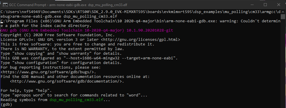
<install_dir>/boards/evkmimxrt595\dsp_examples\mu_polling\cm33\armgcc\debug - Run the command "
arm-none-eabi-gdb.exe <demo_name>.elf". For this example, it is "arm-none-eabi-gdb.exe dsp_mu_polling_cm33.elf". -
Run the next gdb commands:
- "target remote localhost:2331"
- "load"
- "monitor reset"
-
Execute the "monitor go" command to start the example application.
The mu_polling cm33 application is now running.

Build the DSP Application
To build and debug the DSP application follow the instructions of chapter “2. Build the DSP Application” at MCUXpresso tutorial on this same section.
Modify a SDK Example
4.1 Clone an Example Project From MCUXpresso SDK
Option A: Use the MCUXpresso IDE to clone an example project.
Use MCUXpresso IDE
Build an Example Application
The following steps will guide you through the manipulation of the general-purpose outputs. The example sets up a SCTimer to generate a PWM signal and change a LED brightness.
- Find the Quickstart Panel in the lower left-hand corner
- Then click on Import SDK examples(s)…
- Click on the evkmimxrt595 board to select that you want to import an example that can run on that board, and then click on Next.
-
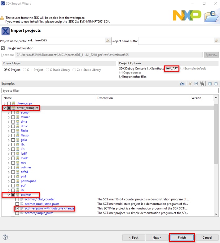
Use the arrow button to expand the
driver_examplescategory, then expand thesctimerexamples, click on the check box next tosctimer_pwm_with_dutycycle_changeto select it. To use the UART for printing (instead of the default semihosting), Select UART as the SDK Debug Console checkbox under the project options. Then, click on Finish. - Click on the “
evkmimxrt595_sctimer_pwm_with_duty_cycle_change” project in the Project Explorer View and build, compile, and run the demo as described previously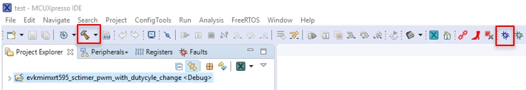
- You should see the RED LED changing the brightness.
- Terminate the debug session
Option B: Use the MCUXpresso Config Tool to clone an existing MCUXpresso SDK example for use with third party IDEs. Please use MCUXpresso Config Tool v9.0 or above.
Use MCUXpresso Config Tool
The following steps will guide you through the manipulation of the general-purpose outputs. The example sets up a SCTimer to generate a PWM signal and change a LED brightness.
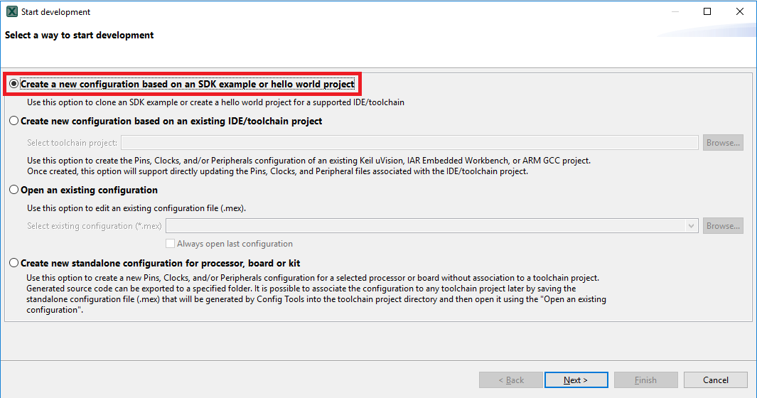
- Open the MCUXpresso Config Tool
- In the wizard that comes up, select the “Create a new configuration based on an SDK example or hello word project” radio button and click on Next.
-
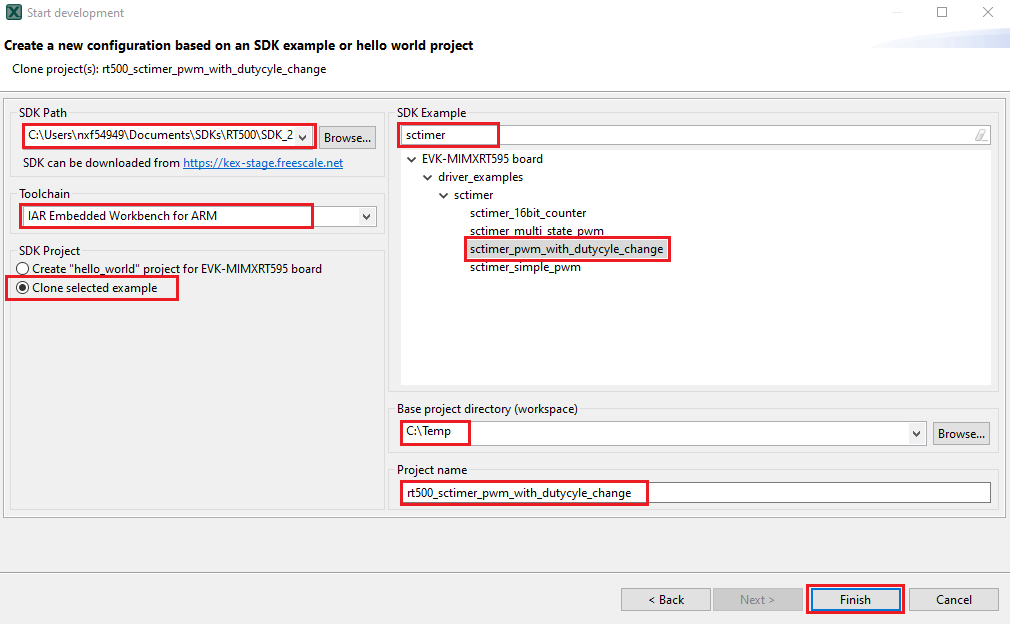
On the next screen, select the location of the MCUXpresso SDK that you had unzipped earlier. Then select the IDE that is being used. Note that only IDEs that were selected in the online SDK builder when the SDK was built will be available and click on clone select example
Then select the project to clone. For this example, we want to use the gpio led output project. You can filter for this by typing “sctimer” in the filter box and then selecting the
“sctimer_pwm_with_dutycycle_change”example project. You can then also specify where to clone the project and the name. Then click on Finish. - After cloning go to the directory you selected and open the project for your IDE. Import, compile, and run the project as done in previous sections
- You should see the RED LED changing the brightness
- Terminate the debug session
4.2 Use the Pin Tool
Now, let's use the Pins tool that is part of the MCUXpresso Config Tool to change the LED that is blinking to a different LED color.
Use MCUXpresso IDE Pins Tools
To open pin tools in MCUXpresso IDE:
-
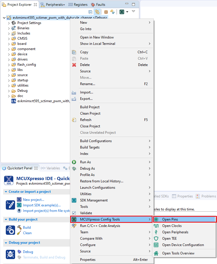
Open the pins tool by right clicking on the
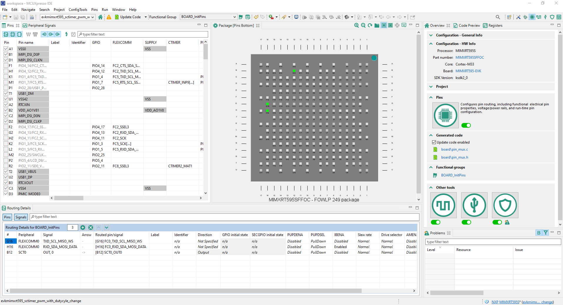
“evkmimxrt595_sctimer_pwm_with_dutycycle_change”project, and selecting “MCUXpresso Config Tools” and then “Open Pins” - The pins tool should now display the pin configuration for the sct project
To open pin tools in MCUXpresso Config tools:
- Open the MCUXpresso Config Tool
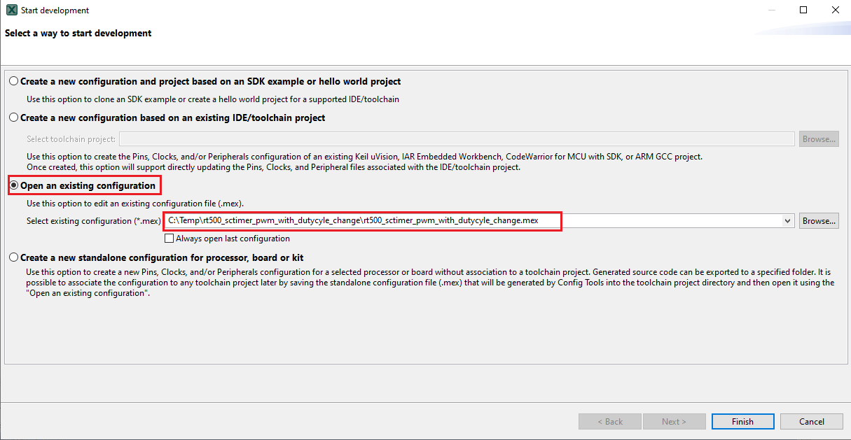
- In the wizard that comes up, select the “Open existing configuration” radio button, then select the project that you had clone and click on Next
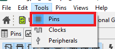
- Open the pins tool by selecting Tools->Pins from the toolbar
- The pins tool should now display the pin configuration for the sctimer project
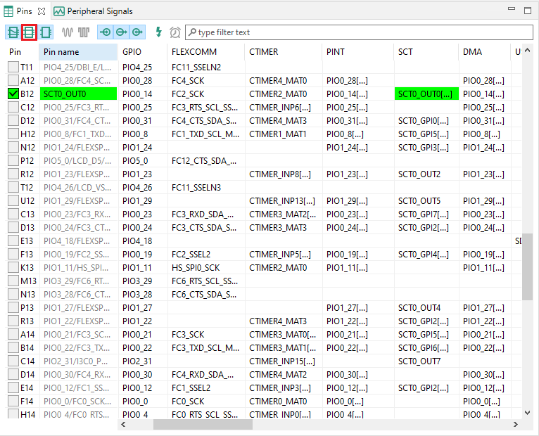
- We'll use MCUXpresso IDE for the rest of the instructions, but the same steps can be done in MCUXpresso Config tools for third party IDEs. In the Pins view deselect “Show dedicated pins” and “Show no routed pins” checkboxes to see only the routed pins. Routed pins have a check in a green box next to the pin name. The functions selected for each routed pin are highlighted in green
- In the current configuration, PIO0_14 is routed as a SCT0_OUT0. Let's disable, PIO0_14, and change the mux setting of PIO1_0 to use its SCT0_OUT7 functionality
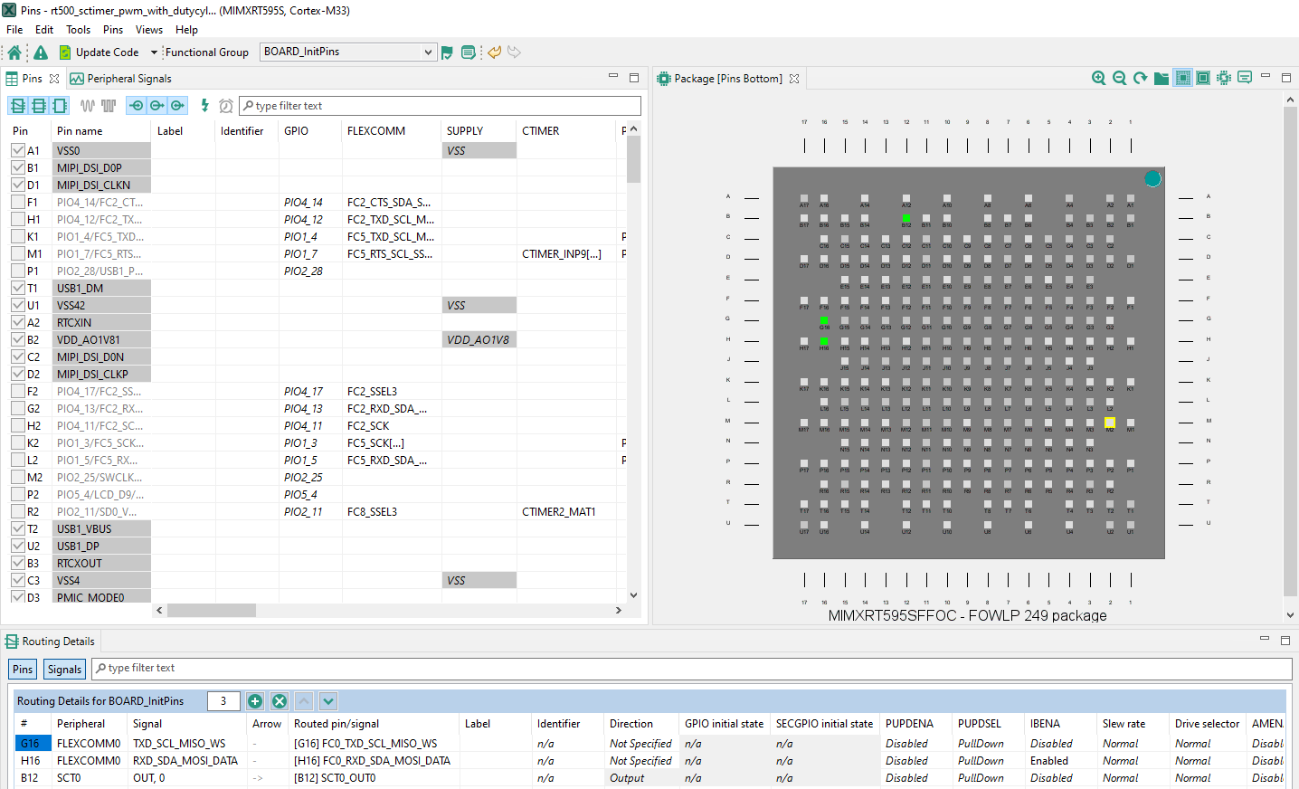
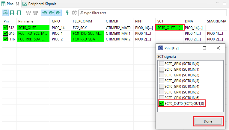
- Disable PIO0_14 by clicking the “SCT0_OUT0” field under the SCT column. A new window will appear. Deselect the SCT0_OUT0 checkbox and click on Done. The pin will then be disabled (pin will no longer have check in box) and thus disappear from the list
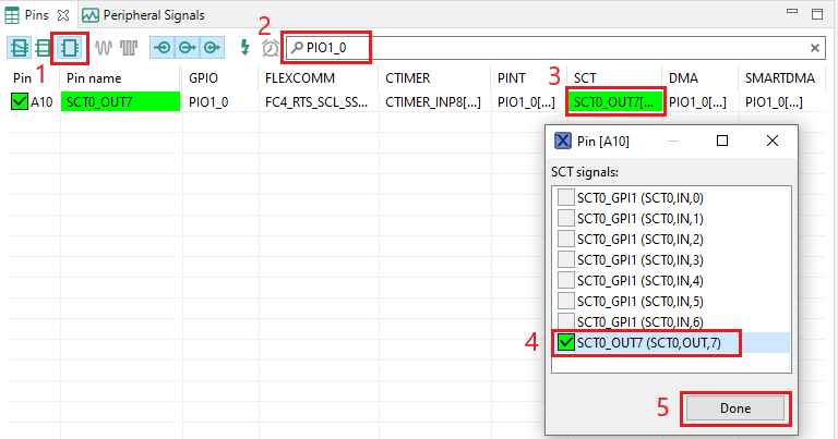
- Now, route PIO1_0 as a SCT_OUT7. First, select the “Show not routed pins” so that all the pins are displayed again. Then, search PIO1_0 in the pins view. Finally, click the box under the SCT column “SCT_OUT7”. The box will highlight in green, and a check will appear next to the pin
- Now it's time to implement these changes into the project by exporting the new updated
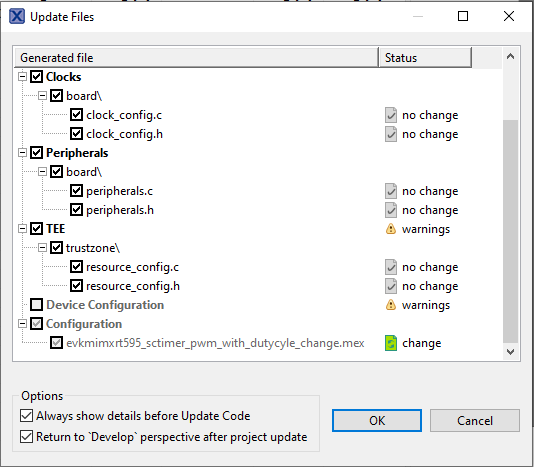
pin_mux.candpin_mux.hfiles that are generated by the Pins tool. Click on Update Project in the menu bar
-
The screen that pops up will show the files that are changing and you can click on “diff” to see the difference between the current file and the new file generated by the Pins tool. Click on “OK” to overwrite the new files into your project
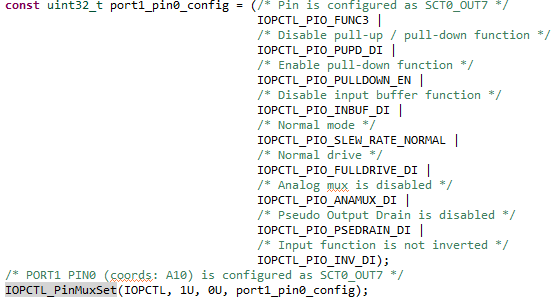
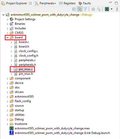
- Now inside the IDE, open the
pin_mux.cfile under board folder - Search for BOARD_InitPins(void) function. Note that when we change the sct routed pin in the tool the PIO0_14 was selected and configured as SCT_OUT (red led). Now, we have the declaration of PIO1_0 and configured as SCT_OUT (green led)
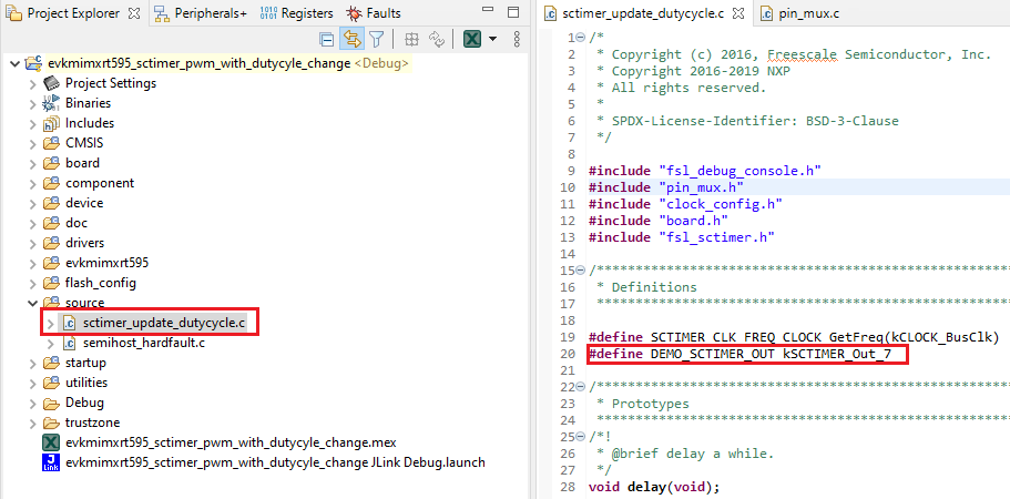
- Open
sctimer_update_dutycycle.cfile and change macro DEMO_SCTIMER_OUT to kSCTIMER_Out_7 - Build and download the project as done in the previous section
- Run the application. You should now see the GREEN LED changing the brightness
- Terminate the debug session
4.3 Use the Clocks Tool
Next use the Clocks tool that is part of the MCUXpresso Config Tool to change the clock settings and change the rate that the LED blinks.
Use MCUXpresso IDE Pins Tools
To open pin tools in MCUXpresso IDE:
-
Open the pins tool by right clicking on the
“evkmimxrt595_sctimer_pwm_with_dutycycle_change”project, and selecting “MCUXpresso Config Tools” and then “Open Pins” - The pins tool should now display the pin configuration for the sct project.
To open pin tools in MCUXpresso Config tools:
- Open the MCUXpresso Config Tool.
- In the wizard that comes up, select the “Open existing configuration” radio button, then select the project that you had clone and click on Next.
- Open the pins tool by selecting Tools->Pins from the toolbar.
- The pins tool should now display the pin configuration for the sctimer project.
Use the pins tools to modify the LED routed pin:
- We'll use MCUXpresso IDE for the rest of the instructions, but the same steps can be done in MCUXpresso Config tools for third party IDEs. In the Pins view deselect “Show dedicated pins” and “Show no routed pins” checkboxes to see only the routed pins. Routed pins have a check in a green box next to the pin name. The functions selected for each routed pin are highlighted in green
- In the current configuration, PIO0_14 is routed as a SCT0_OUT0. Let's disable, PIO0_14, and change the mux setting of PIO1_0 to use its SCT0_OUT7 functionality
- Disable PIO0_14 by clicking the “SCT0_OUT0” field under the SCT column. A new window will appear. Deselect the SCT0_OUT0 checkbox and click on Done. The pin will then be disabled (pin will no longer have check in box) and thus disappear from the list
- Now, route PIO1_0 as a SCT_OUT7. First, select the “Show not routed pins” so that all the pins are displayed again. Then, search PIO1_0 in the pins view. Finally, click the box under the SCT column “SCT_OUT7”. The box will highlight in green, and a check will appear next to the pin
- Now it's time to implement these changes into the project by exporting the new updated
pin_mux.candpin_mux.hfiles that are generated by the Pins tool. Click on Update Project in the menu bar -
The screen that pops up will show the files that are changing and you can click on “diff” to see the difference between the current file and the new file generated by the Pins tool. Click on “OK” to overwrite the new files into your project
- Now inside the IDE, open the
pin_mux.cfile under board folder - Search for BOARD_InitPins(void) function. Note that when we change the sct routed pin in the tool the PIO0_14 was selected and configured as SCT_OUT (red led). Now, we have the declaration of PIO1_0 and configured as SCT_OUT (green led)
- Open
sctimer_update_dutycycle.cfile and change macro DEMO_SCTIMER_OUT to kSCTIMER_Out_7 - Build and download the project as done in the previous section
- Run the application. You should now see the GREEN LED changing the brightness
- Terminate the debug session
4.4 Success
With the application modified, you will see the MIMXRT595-EVK green RGB LED blinking.
LPCScrypt Tutorial
LPCScrypt Tutorial
LPCScrypt is a command-line based, fast flash, EEPROM, OTP and security programming tool for LPC microcontrollers. It is the recommended tool to program the latest CMSIS-DAP and J-Link firmware.
- Download the LPCScrypt tool using the button below, choose your platform (Windows, MAC OC X, Linux). After the download, run the installer. During the installation the DFU and VCOM drivers will be automatically installed for all platforms.
-
Configure To update the LPC-Link2 debug circuit firmware, unplug the USB cable on
J40and then put on the DFULink jumper.- In the MIMXRT595-EVK,
JP1is the LPCXpresso DFU. ConnectJP1using the jumper. - Reconnect the board to your host computer over the debug link USB connector
J40.
- In the MIMXRT595-EVK,
-
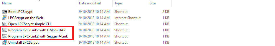
Launch LPCScrypt by double-clicking on the “Boot LPCScrypt” file in the LPCScrypt install
C:\ProgramData\Microsoft\Windows\Start Menu\Programs\LPCScrypt.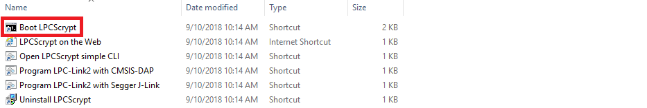
-
In the command shell, run the JLINK script to install the Jlink debug firmware
Note:
- File paths in this document use Windows directory separators, on Linux or Mac OSX these must be replaced with '/.'
- For Windows users, shortcuts to these scripts are available from the LPCScrypt entry on the Start menu.
-
In the command shell, run the JLINK script to install the Jlink debug firmware
- Verify once you select on firmware (in this case J-Link), LPCScrypt command window will show something like below in the console.
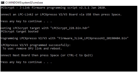
- Ready Once programming is complete, disconnect the board from the host. Remove the DFULink jumper, then reconnect the board to the host computer. You should see the probe enumerate on the host's USB system.
MCUXpresso IDE Terminal Tutorial
MCUXpresso IDE Terminal Tutorial
The most recent versions of MCUXpresso IDE count with a terminal emulation application. This tool can be used to display information sent from your NXP development platform's virtual serial port.
- Open the MCUXpresso IDE
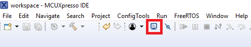
- Launch the MCUXpresso IDE terminal by clicking on the “Open a Terminal” button on the top of the IDE or press “Ctrl + Alt + Shift + T.”
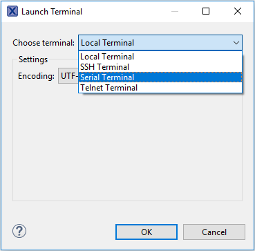
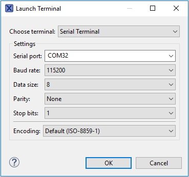
- Select Serial Terminal
- Configure the serial port settings (using the LPC-Link2 COM port number) to 115200 baud rate, 8 data bits, no parity and 1 stop bit, then press “OK” button
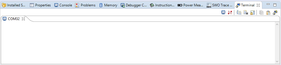
- Verify that the connection is open. If connected, MCUXpresso IDE will look like the figure below at the Terminal view
- You're ready to go

Tera Term Tutorial
Tera Term Tutorial
Tera Term is a very popular open source terminal emulation application. This program can be used to display information sent from your NXP development platform's virtual serial port.
- Download Tera Term from SourceForge. After the download, run the installer and then return to this webpage to continue
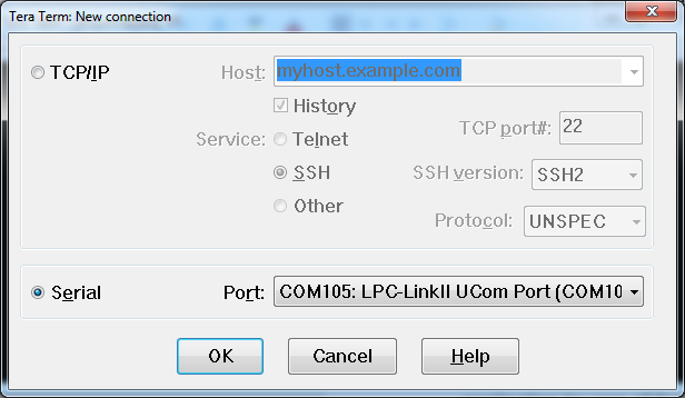
- Launch Tera Term. The first time it launches, it will show you the following dialog. Select the serial option. Assuming your board is plugged in, there should be a COM port automatically populated in the list
- Configure the serial port settings (using the COM port number identified earlier) to 115200 baud rate, 8 data bits, no parity and 1 stop bit. To do this, go to Setup -> Serial Port and change the settings
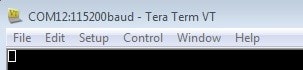
- Verify that the connection is open. If connected, Tera Term will show something like below in it's title bar
PuTTY Tutorial
PuTTY Tutorial
PuTTY is a popular terminal emulation application. This program can be used to display information sent from your NXP development platform's virtual serial port.
- Download PuTTY using the button below. After the download, run the installer and then return to this webpage to continue
- Launch PuTTY by either double clicking on the *.exe file you downloaded or from the Start menu, depending on the type of download you selected
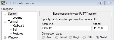
- Configure In the window that launches, select the Serial radio button and enter the COM port number that you determined earlier. Also enter the baud rate, in this case 115200
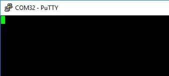
- Click Open to open the serial connection. Assuming the board is connected and you entered the correct COM port, the terminal window will open. If the configuration is not correct, PuTTY will alert you
- You're ready to go
SEGGER J-Link Tutorial
SEGGER J-Link Tutorial
-
Download J-Link software
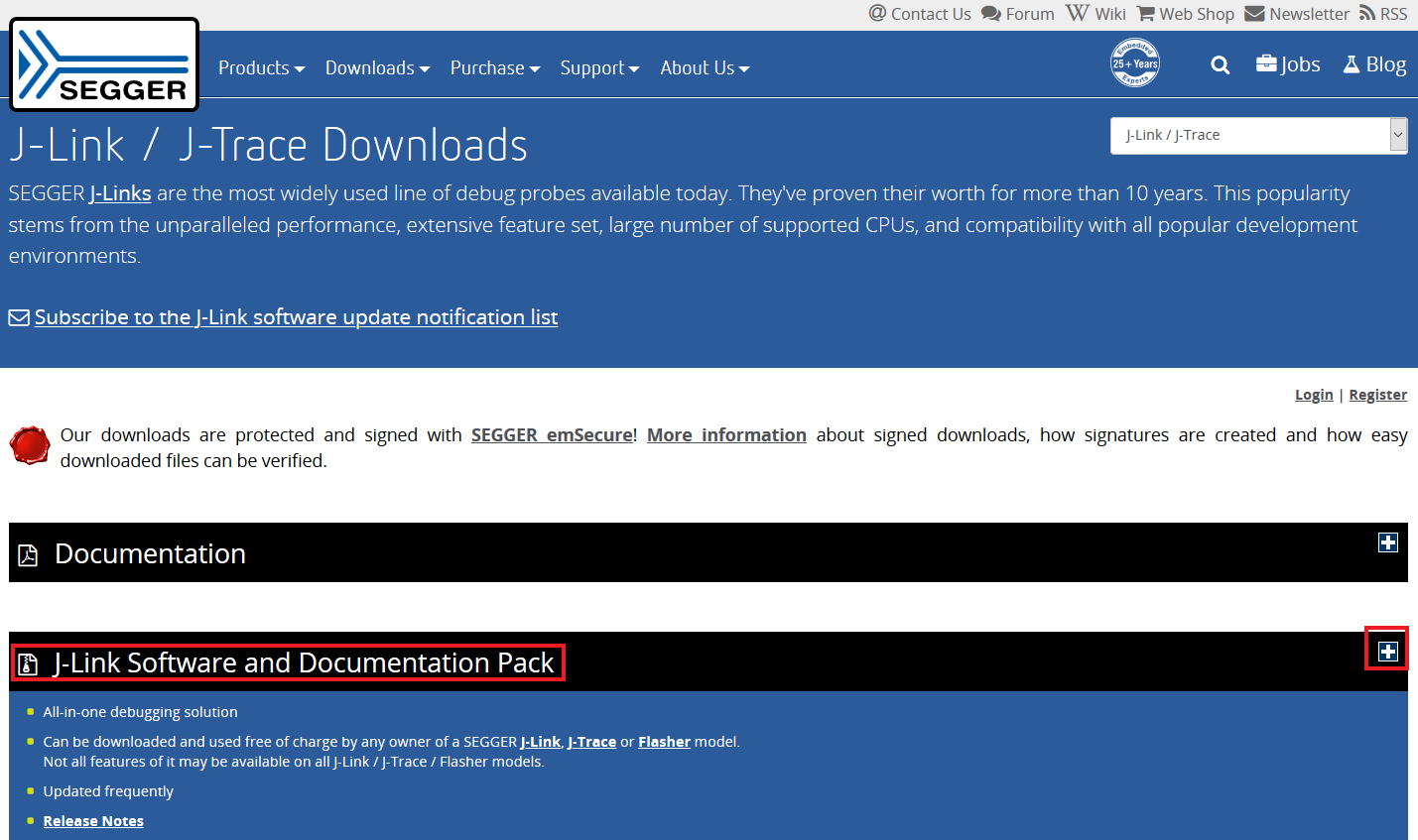
Enter to SEGGER download page: Segger.
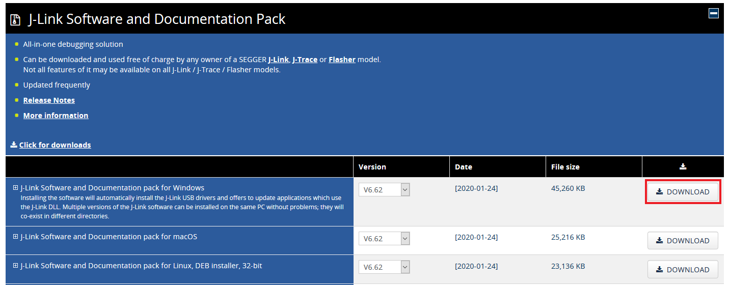
- Expand “J-Link Software and Documentation Pack” section
-
Select the software that matches your OS and download the newest version
Accept terms and download the software
- Execute the
.exefile you just downloaded by doing double-click. Follow the setup instructions until the J-Link installation is complete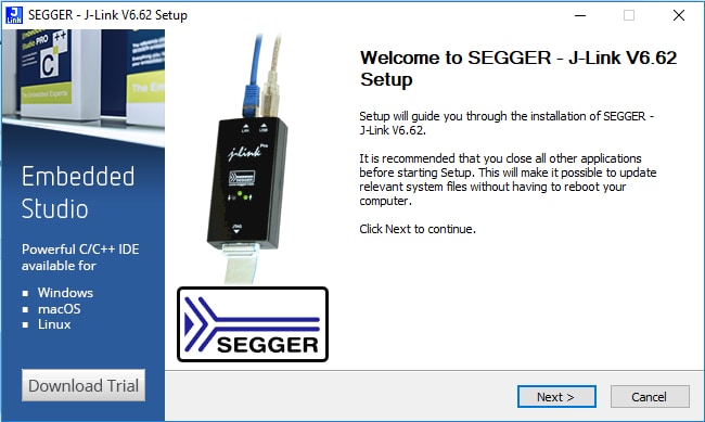
- You're ready to go
Xtensa Xplorer Tutorial
Xtensa Xplorer Tutorial
Cadence® Tensilica® Xplorer is a complete development environment that helps users create application code for high-performance Tensilica® processors. Xplorer is the interface to powerful software development tools such as the XCC compiler, assembler, linker, debugger, code profiler and full set of GUI tools.
Xplorer (including both GUI and command line environment.) is the only available development IDE for the DSP core of MIMXRT500.
-
Create a profile. This is needed to download the Tensilica Tools. Go to the URL
Fusion f1 DSP SDK For RT500
and login. If this is the first time to access, please register first.

You will receive an email confirmation with the activation link from “Tensilica tools”. Click the activation link to complete the registration.
-
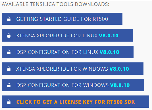
Install Xtensa Xplorer IDE. Once registered, please login and you will see available materials
- Download and install “Xtensa Xplorer IDE 8.0.10” for your operating system
- Download “DSP Configuration” for your operating system. This will be installed later (Step 5)
-
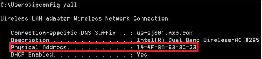
Download a License Key. To generate the correct license file, you should first identify the appropriate MAC for the computer you plan to run Xtensa tools on. Open a Command Prompt and type:
Windows:
Linux:

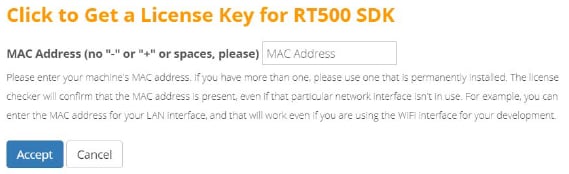
Reload and return to the Tensilica URL: Fusion f1 DSP SDK For RT500 and click on “Get a License Key for RT500 SDK”.

Type your MAC address without "-" or ":" symbols.
-
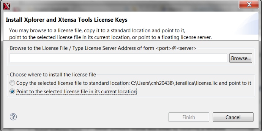
Install License Key. Once the license has been generated and downloaded, open Xplorer IDE and select on menu Help → Xplorer License Keys → License Options → Install Software Keys. Select the license key file and click "Finish".
-
Install RT500 DSP Build Configuration. The build configuration can be installed into the IDE using the 'System Overview' panel which is located on the lower left corner by default. If this panel is not visible, it can be toggled using menu item Window → Show View → System Overview
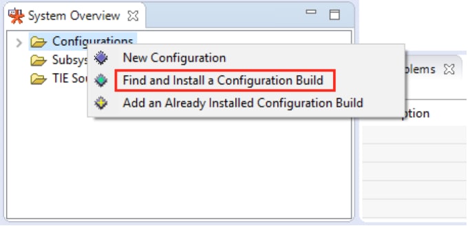
Search the configuration you downloaded at Step 2.
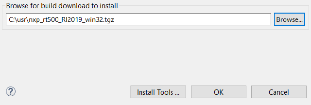
-
Install Xtensa On Chip Debugger Deamon. The Xtensa On Chip Debugger Deamon (xt-ocd), is a powerful gdb-based debugging tool. It is not installed by default with the Xplorer IDE. A self-extracting executable installer is included with the IDE, it is located at:
Windows:
“C:\usr\xtensa\XtDevTools\downloads\RI2019.1\tools\xt-ocd-14.0.1-windows64-installer.exe”Linux:
“~/xtensa/XtDevTools/downloads/RI2019.1/tools/xt-ocd-14.0.1-linux64-installer”At this moment xt-ocd supports J-Link and ARM RVI/DSTREAM probes over Serial Wire Debug (SWD) for RT500. xt-ocd installs support for J-Link probes but does not install the required J-Link drivers which must be installed separately. The RT500 requires J-Link software version 6.92 or newer.
-
Identify the Jlink serial number of your LPC-Link2. Run JLINK commander to check the serial number. It is located at: “
C:\Program Files (x86)\SEGGER\JLink”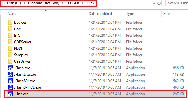
Every EVK/LPC-Link2 will have different Jlink S/N.
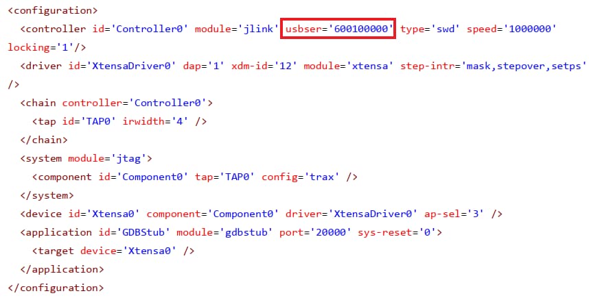
Edit topology file. xt-ocd is configured with an XML input file '
topology.xml'. The file is located in the Xtensa OCD installation directory at“C:\Program Files (x86)\Tensilica\Xtensa OCD Daemon 14.01”You will need to modify this file for your debugger hardware. Using J-link as example, please use this topology.xml file to replace the original file. Or copy one of the examples below
Please note that you need to replace 'usbser section with your own Jlink serial number (9-digit number obtained on the previous step).
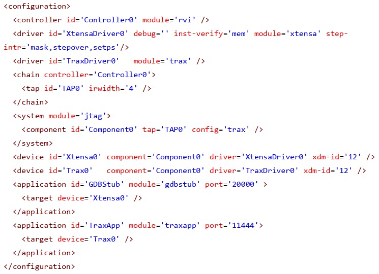
Below is shown another topology.xml example fot ARM RealView ICE (RVI) and DSTREAM debug probes:
Design Resources
Additional Resources
Sensors
Explore the world with a full assortment of NXP sensor solutions. From accelerometers, pressure sensors, touch sensors, and many more, NXP has a sensor solution for your project. Find out more at Sensors
NFC
Near Field Communication is a simple, intuitive technology that lets you interact securely with the world around you with a simple touch. Learn more about NXP's NFC solutions at NFC - Near Field Communication
Wi-Fi
Getting Started with NXP Wi-Fi modules using i.MX RT platform - Let's take your Wi-Fi module for a test drive. This guide uses the Wi-Fi modules and i.MX RT platforms
Support
Forums
Connect with other engineers and get expert advice on designing with i.MX processors and MCUXpresso Software and Tools. Join the community discussion in one of our two dedicated communities: i.RT Community or MCUXpresso Software and Tools Community .