Getting Started with the TEA2208DB1576
Contents of this document
-
Get started
-
Get to Know the Hardware
-
Configure Hardware
Sign in to save your progress. Don't have an account? Create one.
Purchase your TEA2208DB1576
1. Get started
The NXP analog product development boards provide an easy-to-use platform for evaluating NXP products. The boards support a range of analog, mixed-signal and power solutions. They incorporate monolithic integrated circuits and system-in-package devices that use proven high-volume technology. NXP products offer longer battery life, a smaller form factor, reduced component counts, lower cost and improved performance in powering state-of-the-art systems.
This page will guide you through the process of setting up and using the TEA2208DB1576 demo board.
1.1 Kit Contents/packing List
The TEA2208DB1576 contents include:
- Assembled and tested TEA2208DB1576 in an anti-static bag
1.2 Additional Hardware
In addition to the kit contents, the following hardware is necessary or beneficial when working with this kit.
- AC power source, electronic load and digital power meter
- Use NXP standard demo boards, TEA2016DB1519 or TEA1916DB1262 together (optional)
2. Get to Know the Hardware
2.1 Board Features
- Forward conduction losses of the diode rectifier bridge are eliminated
- Very low IC power consumption (2 mW)
- Integrated high-voltage level shifters
- Directly drives all four rectifier MOSFETs
- Very low external part count
- Integrated X-capacitor discharge (2 mA)
- Self-supplying
- Full-wave drive improving total harmonic distortion (THD)
- Undervoltage lockout (UVLO) for high-side and low-side drivers
- Drain-source overvoltage protection (OVP) for all external power MOSFETs
- Gate pull-down currents at start-up for all external power MOSFETs
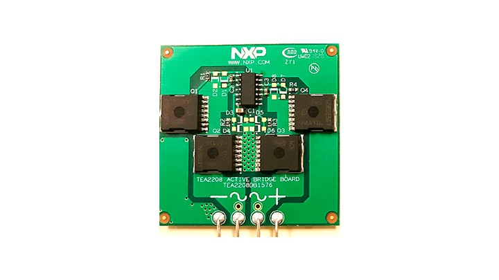
2.2 Board Description
The TEA2208T is an active bridge rectifier controller, which replaces the traditional diode bridge. Using the TEA2208T with low-ohmic high voltage external MOSFETs, significantly improves the efficiency of the power converter as the typical rectifier diode forward conduction losses are eliminated.
Additionally, the TEA2208T incorporates an X-capacitor discharge function. This demo board contains a TEA2208T and four low-ohmic high voltage MOSFETs.
2.3 Board Components
The TEA2208DB1576 demo board consists of the TEA2208T in an SO14 package with four MOSFETs of 600 V/28 mΩ.
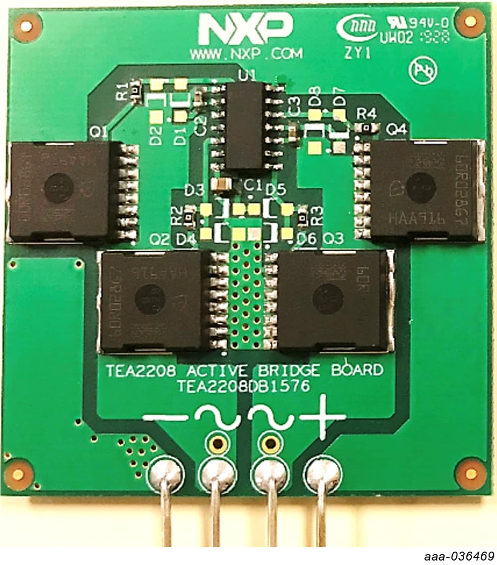
3. Configure Hardware
The demo board contains four 600 V/28 mΩ MOSFETs. It makes the board suitable for universal AC input (100 V to 240 V) and for up to 1 kW as reference. The TEA2208DB1576 demo board contains four leads that can easily replace a traditional diode bridge. The two inside leads are connected to AC mains lines.
The two outside leads are connected to positive and negative rectified voltages. These four leads are pin-to-pin with typical bridge-rectifier diodes pins.

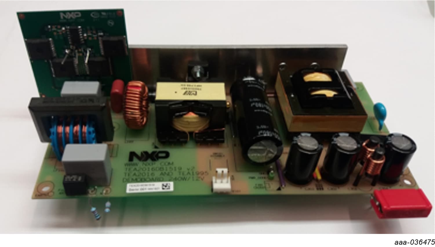
The following figure shows an example of a TEA2208DB1576 demo board mounted on an NXP Semiconductors TEA2016DB1519 demo board.
Design Resources
Additional Resources
Tool Summary Page
- The tool summary page for TEA2208DB1576 board is at TEA2208DB1576
The page provides overview information, technical and functional specifications, ordering information, documentation and software. The Get Started provides quick-reference information applicable to using the TEA2208DB1576 board, including the downloadable assets.
References
In addition to our TEA2208T: Active bridge rectifier controller page, you may also want to visit:
Product pages:
- TEA19161T: Resonant Power Supply Control IC
- TEA2016AAT: Digital LLC+PFC Combo Controller for Resonant Power Supply
- TEA19162T: PFC Controller
- TEA1995T: GreenChip Dual Synchronous Rectifier (SR) Controller
- TEA2095: GreenChip Dual LLC SR Switching Controller
- TEA2208T: