Getting Started with the FRDM-KV11Z
Contents of this document
-
Plug It In
-
Get Software
-
Build, Run
-
Create
Sign in to save your progress. Don't have an account? Create one.
Purchase your FRDM-KV11Z | KV1x | Dev Platform
1. Plug It In
Let's take your FRDM-KV11Z for a test drive! Please follow the detailed actions list below.
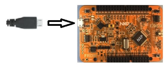
1.1 Attach the USB Cable
1.2 Run the Out-of-Box Demo
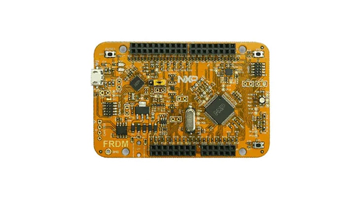
Your FRDM-KV11Z comes loaded with a demonstration project called "frdmkv11z_bubble.bin". The RGB LED will illuminate one color when tilt on one axis and another when tilted on the other. This project was compiled from the demo projects available in the MCUXpresso SDK.
2. Get Software
The software and tools installation are detailed in the steps below.
2.1 Jump Start Your Design with the MCUXpresso SDK
The MCUXpresso SDK is complimentary and includes full source code under a permissive open source license for all hardware abstraction and peripheral driver software. Learn about SDK.
Click below to download a preconfigured SDK release for the FRDM-KV11Z.

You can also use the online SDK Builder to create a custom SDK package for the FRDM-KV11Z using the SDK Builder.
2.2 Install Your Toolchain
NXP offers a complimentary toolchain called MCUXpresso IDE.

Want to use a different toolchain?
No problem! The MCUXpresso SDK includes support for other tools such as IAR , Keil and command-line GCC .

2.3 MCUXpresso Config Tools
The MCUXpresso Config Tools is an integrated suite of configuration tools that guides users in creating new MCUXpresso SDK projects, and also provides pin and clock tools to generate initialization C code for custom board support.

2.4 PC Configuration
Many of the example applications output data over the MCU UART so you'll want to make sure that the driver for the board's virtual COM port is installed. Before you run the driver installer, you must have the board plugged in to your PC.
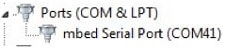
With the serial port driver installed, run your favorite terminal application to view the serial output from the MCU's UART. Configure the terminal to 115,200 baud rate, 8 data bits, no parity, and 1 stop bit. To determine the port number of the FRDM-KV11Z's virtual COM port, open the device manager and look under the "Ports" group.
Not sure how to use a terminal application? Try one of these tutorials: Tera Term Tutorial, PuTTY Tutorial.
3. Build, Run
Please follow the steps below to Build and Run SDK Demos on the FRDM-KV11Z.
3.1 Explore the MCUXpresso SDK Example Code
The MCUXpresso SDK comes with a long list of example applications code. To see what's available, browse
to the SDK boards folder of your SDK installation and select your board, the FRDM-KV11Z:
<sdk_install_directory>/boards/frdmkv11z.
To learn more about specific example code, open the readme.txt file in an example's directory.
3.2 Build, Run and Debug MCUXpresso SDK Examples
If one or more of the demo applications or driver examples sounds interesting, you're probably wanting to know how you can build and debug yourself. The Getting Started with MCUXpresso SDK guide provides easy, step-by-step instructions on how to configure, build, and debug demos for all toolchains supported by the SDK.
Use the guide below to learn how to open, build and debug an example application using the MCUXpresso IDE.
Running a demo using MCUXpresso IDE
Import the MCUXpresso SDK
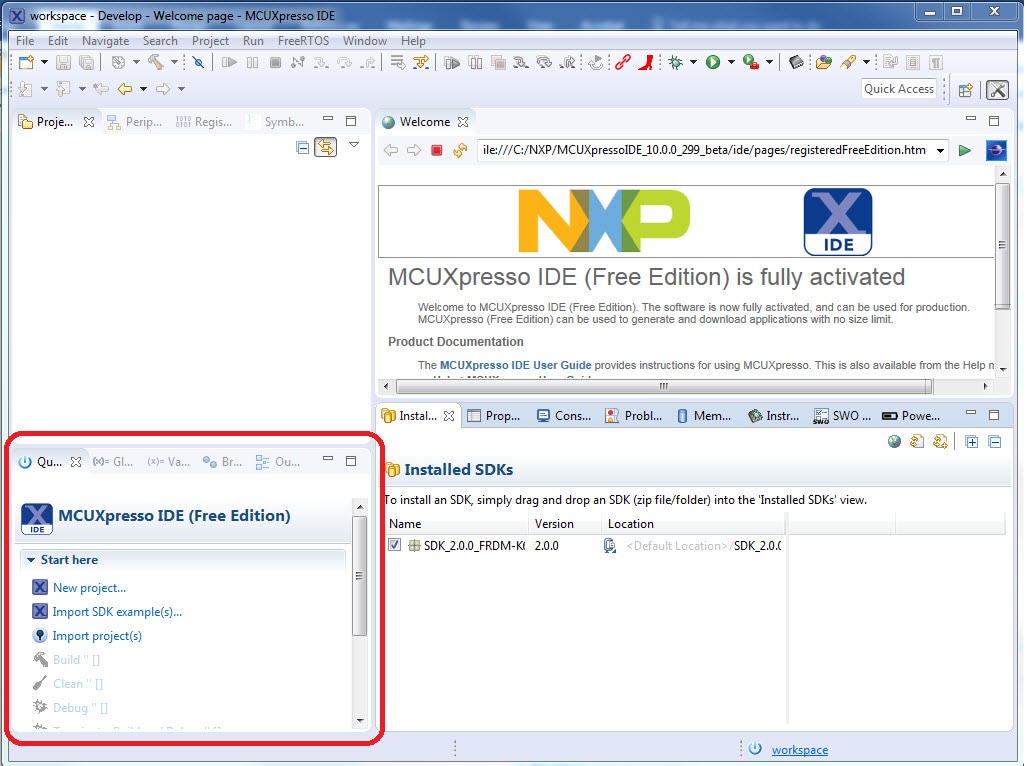
- Open up the MCUXpresso IDE
- Switch to the Installed SDKs view within the MCUXpresso IDE window
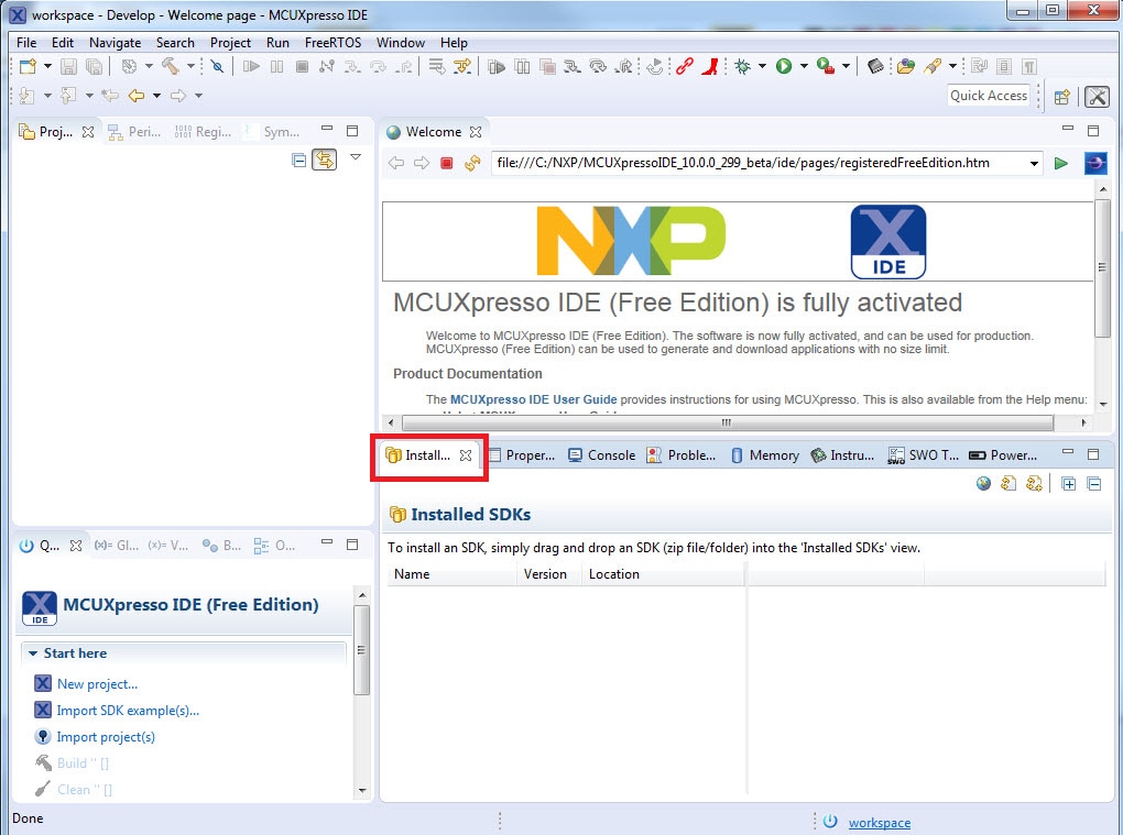
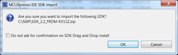
- Open Windows Explorer, and drag and drop the FRDM-KV11Z SDK (unzipped) file into the "Installed SDKs" view
- You will get the following pop-up. Click OK to
continue
the import:
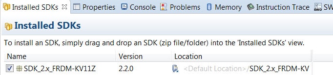
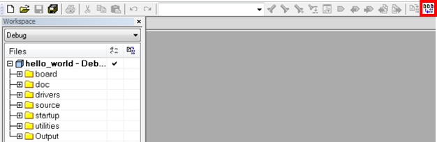
- The installed SDK will appear in the Installed SDKs view as shown
below:
2. Build an Example Application
The following steps will guide you through opening the hello_world example.
-
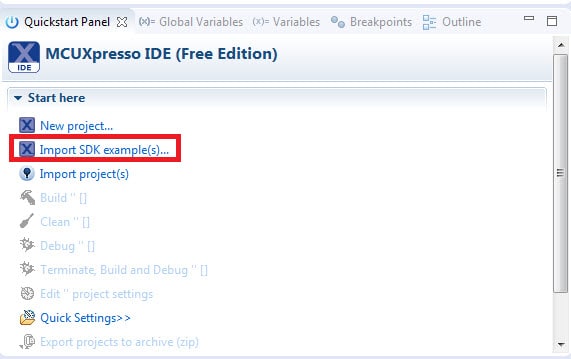
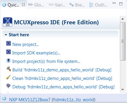
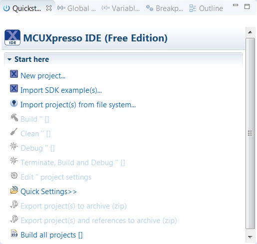
Find the Quickstart Panel in the lower left hand corner
-
Then, click on Import SDK examples(s)
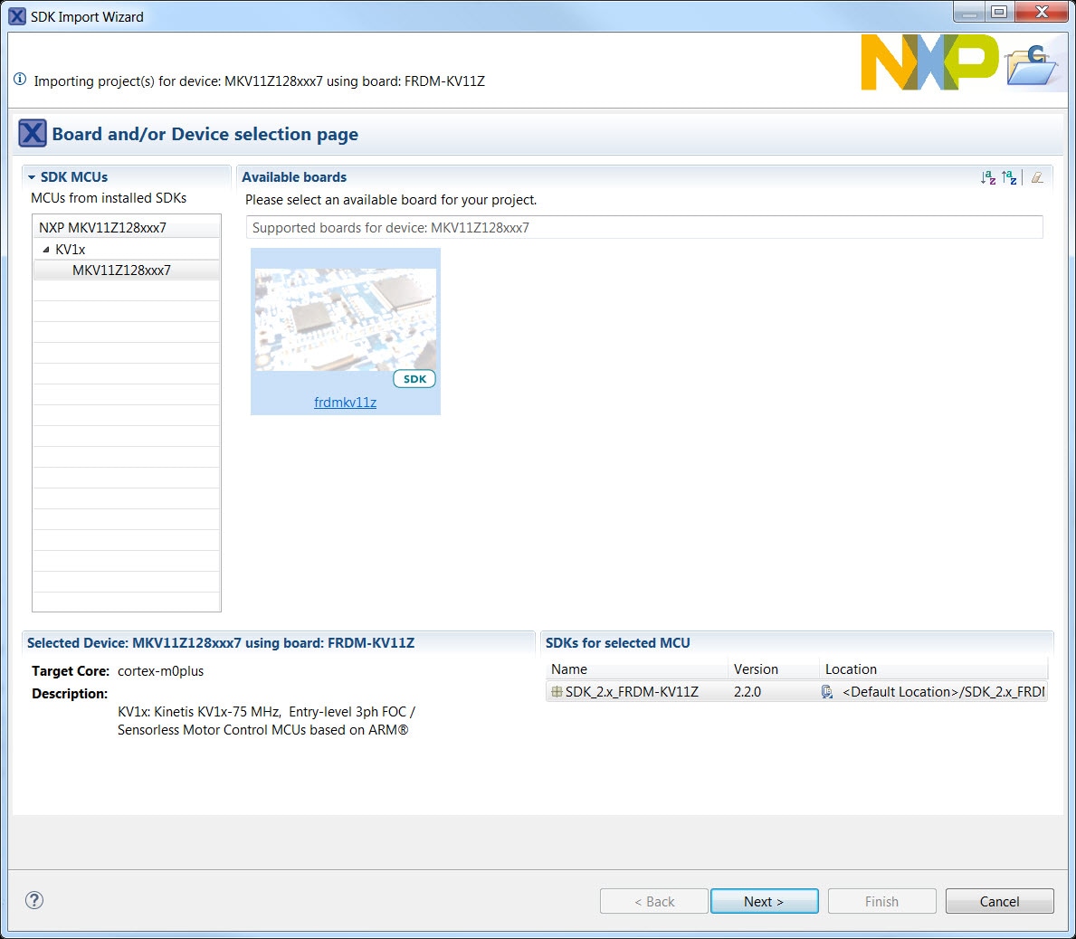
-
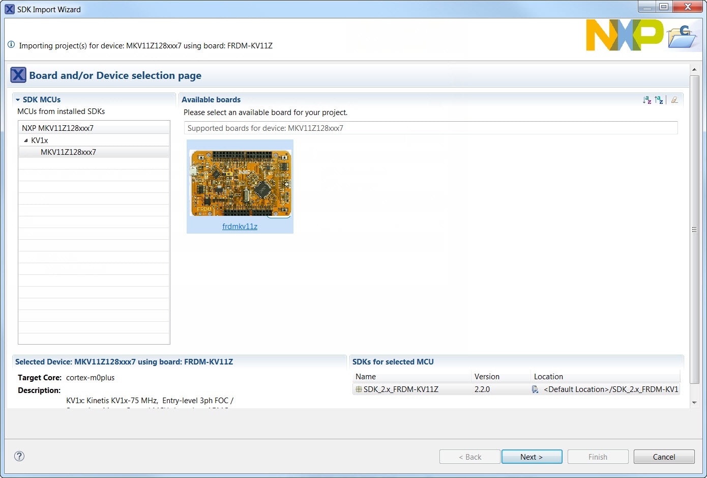
Click on the frdmkv11z board to select that you want to import an
example
that can run on that board, and then click Next
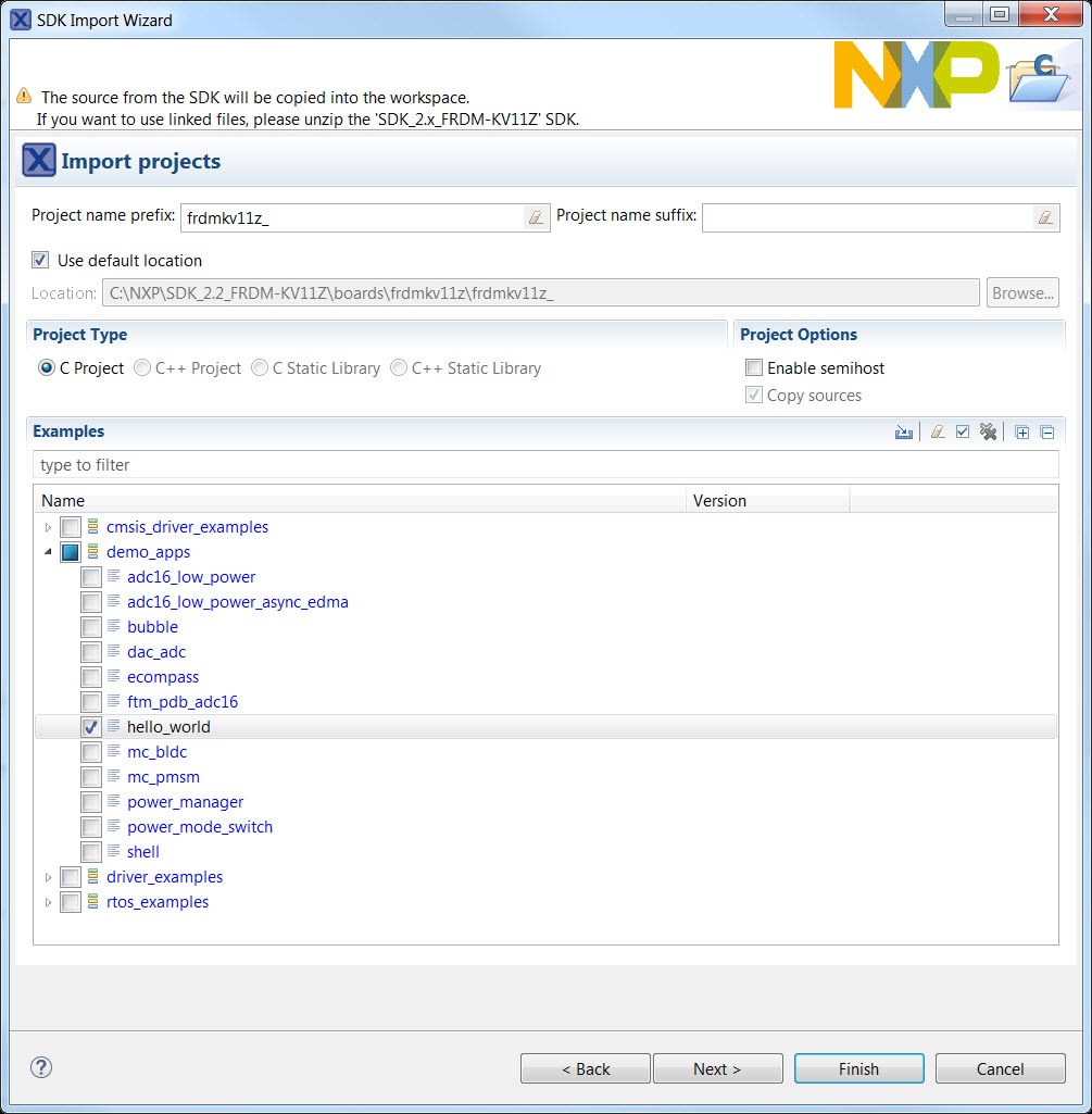
-
Use the arrow button to expand the "demo_apps"
category,
and then click the checkbox next to 'hello_world'
to
select that project. To use the UART for printing (instead of
the
default semihosting), clear the "Enable
semihost" checkbox under the project options.
Then,
click Next
-
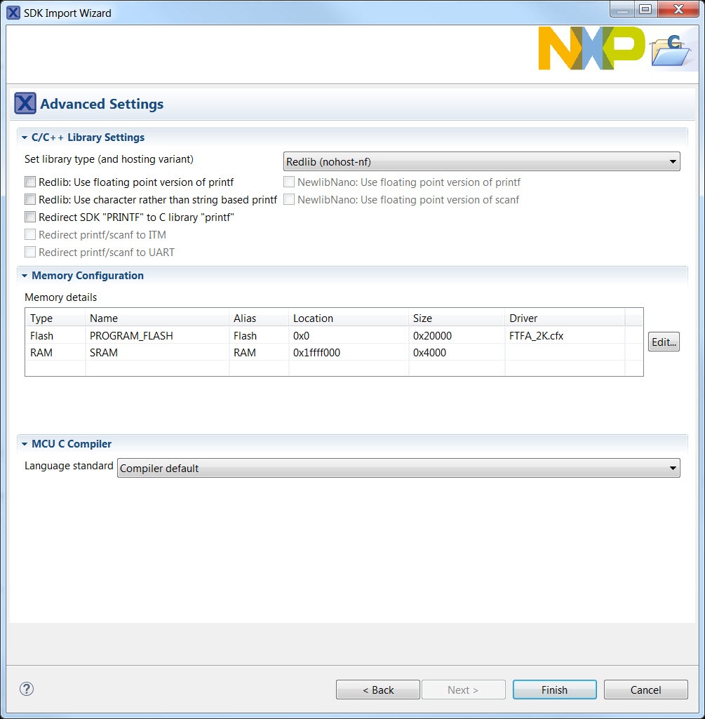
On the Advanced Settings wizard, clear the checkbox
"Redirect SDK "PRINTF" to C library
"printf"" in order to use the
MCUXpresso
SDK console functions for printing instead of generic C library
ones.
Then, click Finish
-
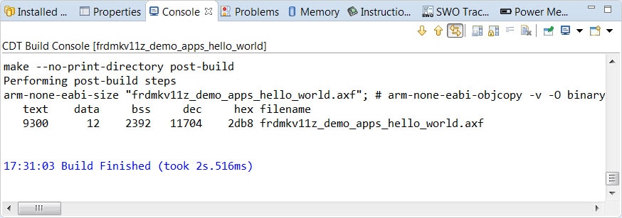
Now, build the project by clicking on the project name and then
click on
the Build icon
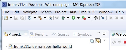
-
You can see the status of the build in the Console tab
Run an Example Application
- Now that the project has been compiled, you can now flash it to the board and run it
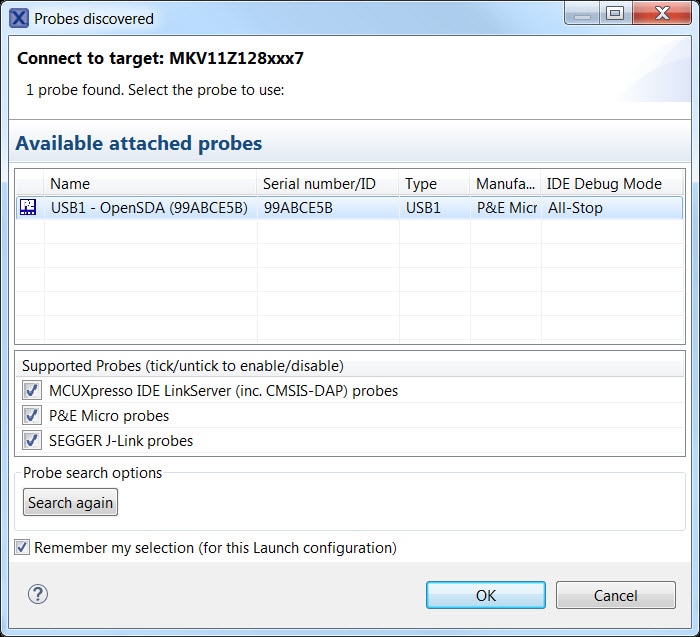
- Make sure the FRDM-KV11Z board is plugged in, and click on
"Debug
"frdmkv11z_demo_apps_hello_world" [Debug]"
-
MCUXpresso IDE will probe for connected boards and should find
the
OpenSDA debug probe that is part of the integrated OpenSDA
circuit on
the FRDM-KV11Z. Click OK to continue
-
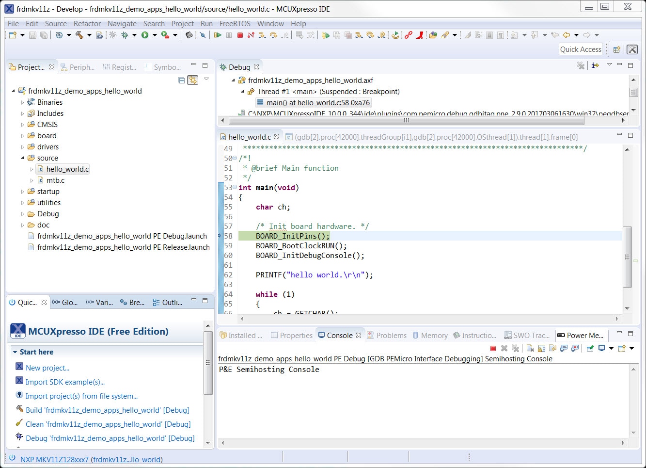
The firmware will be downloaded to the board and the debugger will
start
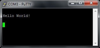
- Open up a terminal program and connect to the COM port the board enumerated as. Use 115,200 baud 8 data bits, no parity and 1 stop bit
-
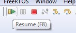
Start the application by clicking the "Resume" button:
-
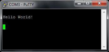
The hello_world application is now running and a banner is
displayed on
the terminal. If this is not the case, check your terminal
settings and
connections
-
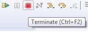
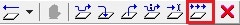
Use the controls in the menu bar to pause, step into, and step
over
instructions, and then stop the debugging session by click on
the
Terminate icon:
Using a different toolchain?
Running a demo using IAR
Build an Example Application
The following steps will guide you through opening the hello_world application. These steps may change slightly for other example applications as some of these applications may have additional layers of folders in their path.
-
If not already done, open the desired example application workspace. Most example application workspace files can be located using the following path:
<install_dir>/boards/<sdk_board_name>/<example_type>/<application_name>/iarUsing the hello_world demo as an example, the path is:
<install_dir>/boards/frdmkv11z/demo_apps/hello_world/iar -
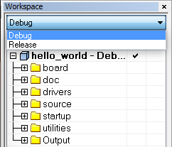
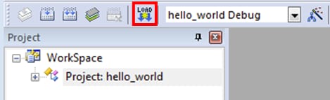
Select the desired build target from the drop-down. For this example,
select
the "hello_world - Debug" target
-
To build the application, click the "Make" button, highlighted in red
below
- The build will complete without errors
Run an Example Application
The FRDM-KV11Z board comes loaded with the P&E bootloader and OpenSDA debug interface from the factory. If you have changed the debug OpenSDA application on your board, visit OpenSDA for information on updating or restoring your board to the factory state.
- Connect the development platform to your PC via USB cable between the "SDAUSB" USB port on the board and the PC USB connector
-
Open the terminal application on the PC (such as PuTTY or Tera Term)
and
connect to the debug COM port you determined earlier. Configure the
terminal
with these settings:
- 115,200 baud rate
- No parity
- 8 data bits
- 1 stop bit
-
Click the "Download and Debug" button to download the application to
the
target

-
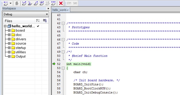
The application is then downloaded to the target and automatically
runs to
the main() function
-
Run the code by clicking the "Go" button to start the application
-
The hello_world application is now running and a banner is displayed
on the
terminal. If this is not the case, check your terminal settings and
connections

Running a demo using Keil® MDK/µVision®
Install CMSIS device pack
After the MDK tools are installed, Cortex® Microcontroller Software Interface Standard (CMSIS) device packs must be installed to fully support the device from a debug perspective. These packs include things such as memory map information, register definitions and flash programming algorithms. Follow these steps to install the appropriate CMSIS pack.
-
Open the MDK IDE, which is called µVision. In the IDE,
select the
"Pack Installer" icon
-
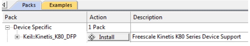
In the Pack Installer window, navigate to the section with the
Kinetis
packs (they are in alphabetical order). The Kinetis packs start
with
"Keil::Kinetis" and are followed by the MCU family
name, for
example "Keil::Kinetis_K80_DFP". Because this
example uses
the FRDM-KV11Z platform, the KV1x family pack is selected. Click
on the
"Install" button next to the pack. This process
requires an
internet connection to successfully complete
- After the installation finishes, close the Pack Installer window and return to the µVision IDE
Build the Example Application
The following steps will guide you through opening the hello_world application. These steps may change slightly for other example applications as some of these applications may have additional layers of folders in their path.
-
If not already done, open the desired demo application workspace in:
<install_dir>/boards/<sdk_board_name>/<example_type>/<application_name>/mdkThe workspace file is named <application_name>.uvmpw, so for this specific example, the actual path is:
<install_dir>/boards/frdmk82f/demo_apps/hello_world/iar/hello_world.uvmpw -
To build the demo project, select the "Rebuild" button,
highlighted in
red

- The build will complete without errors
Run an Example Application
The FRDM-KV11Z board comes loaded with the P&E bootloader and OpenSDA debug interface from the factory. If you have changed the debug OpenSDA application on your board, visit OpenSDA for information on updating or restoring your board to the factory state.
- Connect the development platform to your PC via USB cable between the "SDAUSB" USB port on the board and the PC USB connector
-
Open the terminal application on the PC (such as PuTTY or
Tera Term) and
connect to the debug COM port you determined earlier. Configure
the
terminal with these settings:
- 115,200 baud rate
- No parity
- 8 data bits
- 1 stop bit
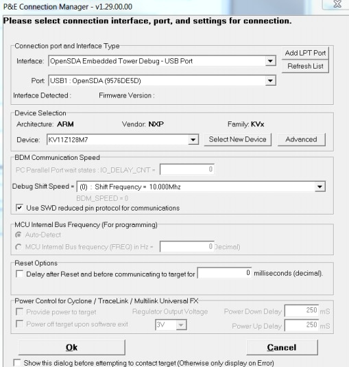
- Open the Options for target "hello_world Debug" and go to the Debug Tab. Select "Use PEMicro Debugger" and click on "Settings". Select the "OpenSDA Embedded FRDM debug - USB Port" and click on "Select New Device" and choose device 'KV11Z128M7'. Then, press OK
-
After the application is properly built and debug setting is
complete, click
the "Download" button to download the application to the target
-
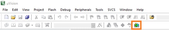
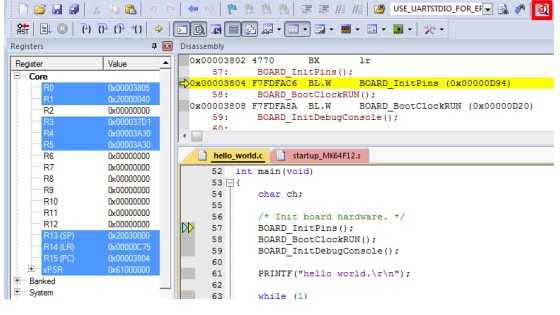
After clicking the "Download" button, the application downloads
to the
target and should be running. To debug the application, click
the
"Start/Stop Debug Session" button, highlighted in red
-
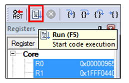
Run the code by clicking the "Run" button to start the
application
-
The hello_world application is now running and a banner is
displayed on
the terminal. If this is not the case, check your terminal
settings and
connections

Run a demo using Arm® GCC
Set Up Toolchain
This section contains the steps to install the necessary components required to build and run a KSDK demo application with the Arm GCC Toolchain, as supported by the Kinetis SDK. There are many ways to use Arm GCC tools, but this example focuses on a Windows environment. Though not discussed here, GCC tools can also be used with both Linux OS and Mac OSX.
Install GCC Arm Embedded Toolchain
Download and run the installer from Arm GNU Toolchain . This is the actual toolchain (i.e., compiler, linker, etc.). The GCC Toolchain should correspond to the latest supported version, as described in the Kinetis SDK Release Notes.
Install MinGW
The Minimalist GNU for Windows (MinGW) development tools provide a set of tools that are not dependent on third party C-Runtime DLLs (such as Cygwin). The build environment used by the KSDK does not utilize the MinGW build tools, but does leverage the base install of both MinGW and MSYS. MSYS provides a basic shell with a Unix-like interface and tools.
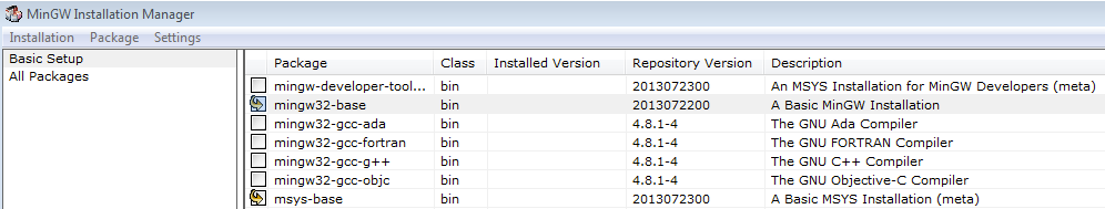
- Download the latest MinGW mingw-get-setup installer from MinGW - Minimalist GNU for Windows Files
- Run the installer. The recommended installation path is C:\MinGW, however, you may install to any location
-
Ensure that the "mingw32-base" and "msys-base" are selected under
Basic
Setup
-
Click "Apply Changes" in the "Installation" menu and follow the
remaining
instructions to complete the Installation
-
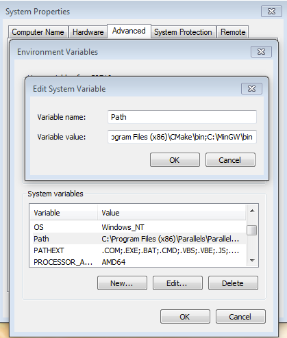
Add the appropriate item to the Windows operating system Path environment variable. It can be found under "Control Panel → System and Security → System → Advanced System Settings" in the "Environment Variables..." section. The path is:
<mingw_install_dir>\binAssuming the default installation path, C:\MinGW, an example is shown below. If the path is not set correctly, the toolchain does not work
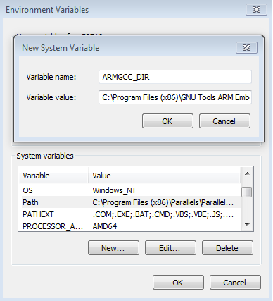
Add a New Environment Variable for ARMGCC_DIR
-
Create a new system environment variable and name it ARMGCC_DIR. The value of this variable should point to the Arm GCC Embedded Toolchain installation path, which, for this example, is:
C:\Program Files (x86)\GNU Tools Arm Embedded\4.9 2015q3Reference the installation folder of the GNU Arm GCC Embedded tools for the exact path name of your installation
Install CMake
- Download CMake 3.0.x from CMake
-
Install CMake, ensuring that the option "Add CMake to system
PATH" is
selected when installing. It's up to the user to select
whether it's
installed into the PATH for all users or just the current
user. In
this example, the assumption is that it's installed for all
users
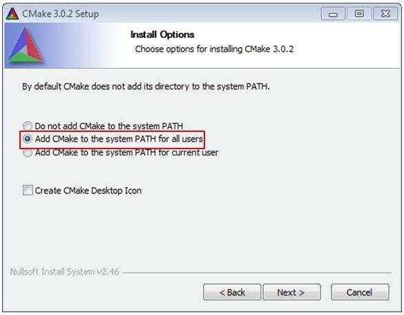
- Follow the remaining instructions of the installer
- You may need to reboot your system for the PATH changes to take effect
Build an Example Application
To build an example application, follow these steps.
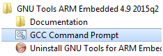
-
If not already running, open a GCC Arm Embedded Toolchain
command
window. To launch the window, from the Windows operating system
Start
menu, go to "Programs → GNU Tools Arm Embedded <version>"
and select
"GCC Command Prompt"
-
Change the directory to the example application project directory, which has a path like this:
<install_dir>/boards/<board_name>/<example_type>/<application_name>/armgccFor this guide, the exact path is:
<install_dir>/boards/frdmk82f/demo_apps/hello_world/armgcc -
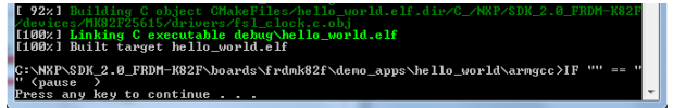
Type "build_debug.bat" on the command line or double click on the
"build_debug.bat" file in Windows operating system Explorer to
perform
the build. The output is shown in this figure:
Run an Example Application
The GCC tools require a J-Link debug interface. To update the OpenSDA firmware on your board to the latest J-Link app, visit OpenSDA. After installing the J-Link OpenSDA application, download the J-Link driver and software package from Segger Downloads .
- Connect the development platform to your PC via USB cable between the "SDAUSB" USB port on the board and the PC USB connector
-
Open the terminal application on the PC (such as PuTTY or Tera Term)
and
connect to the debug COM port you determined earlier. Configure the
terminal
with these settings:
- 115,200 baud rate
- No parity
- 8 data bits
- 1 stop bit
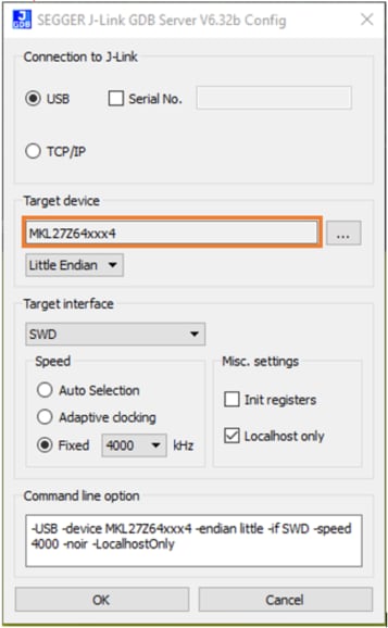
- Open the J-Link GDB Server application. Assuming the J-Link software is installed, the application can be launched by going to the Windows operating system Start menu and selecting "Programs →; SEGGER → J-Link <version> J-Link GDB Server"
-
Modify the settings as shown below. The target device selection
chosen for
this example is the "MK82FN256xxx15" and uses the SWD interface
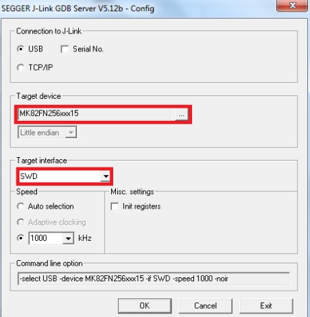
-
After it is connected, the screen should resemble this figure:
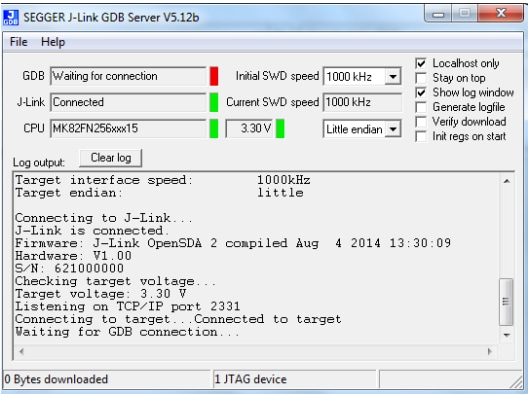
-
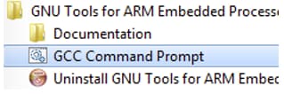
If not already running, open a GCC Arm Embedded Toolchain command
window. To
launch the window, from the Windows operating system Start menu, go
to
"Programs → GNU Tools Arm Embedded <version>" and select "GCC
Command
Prompt"
-
Change to the directory that contains the demo application output. The output can be found in using one of these paths, depending on the build target selected:
<install_dir>/<example_type>/<application_name>/armgcc/debug<install_dir>/<example_type>/<application_name>/armgcc/releaseFor this example, the path is:
<install_dir>/boards/frdmk82f/demo_apps/hello_world/armgcc/debug -
Run the command "arm-none-eabi-gdb.exe <demo_name>.elf". For this
example, it
is "arm-none-eabi-gdb.exe hello_world.elf"
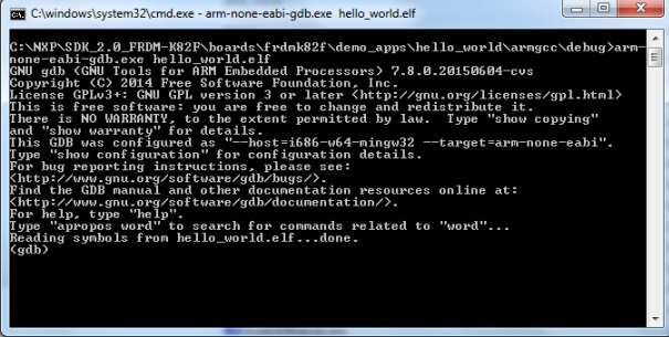
-
Run these commands:
- target remote localhost:2331
- monitor reset
- monitor halt
- load
- monitor reset
- monitor go
- The application is now downloaded and halted at the reset vector. Execute the "monitor go" command to start the example application
- The hello_world application is now running and a banner is displayed in the terminal window
4. Create
4.1 Clone an Example Project from MCUXpresso SDK
Option A: Use the MCUXpresso IDE to clone an example project.
Use MCUXpresso IDE
- Open the MCUXpresso IDE
- Click Import SDK Example(s) from the QuickStart Panel
- Select the FRDM-KV11Z board in the Import Wizard. Then, select Next
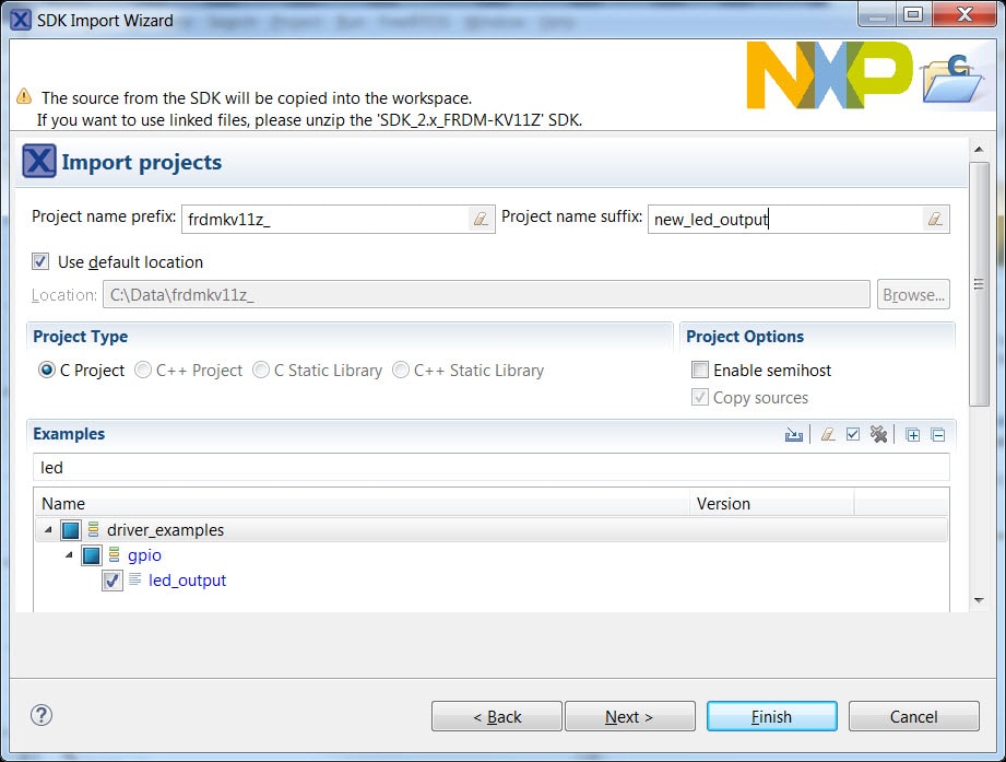
- Type 'led' into the search bar, and
select the
"led_output" project under the gpio
driver
example. Then, select Next. This will create a new
standalone copy of this LED project and put it into the MCUXpresso
workspace. To use the UART for printing (instead of the default
semihosting), clear the "Enable
semihost"
checkbox under the project options. Then, click Next
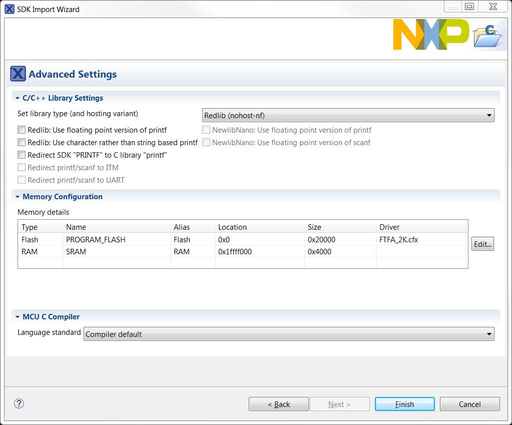
- On the Advanced Settings wizard, clear the checkbox
"Redirect
SDK "PRINTF" to C library
"printf"" in order to use the
MCUXpresso SDK
console functions for printing instead of generic C library ones.
Then, click
on Finish
- Click on the 'led_output' project in
the
Project Explorer View and build, compile, and run the demo as
described
previously

- You should see a red LED blinking on the board
- Terminate the debug session
Option B: Use the MCUXpresso Config Tool to clone an existing MCUXpresso SDK example for use with third party IDEs.
Use MCUXpresso Config Tools
To clone an existing demo app or driver example for use with a third-party IDE use MCUXpresso Config Tools.
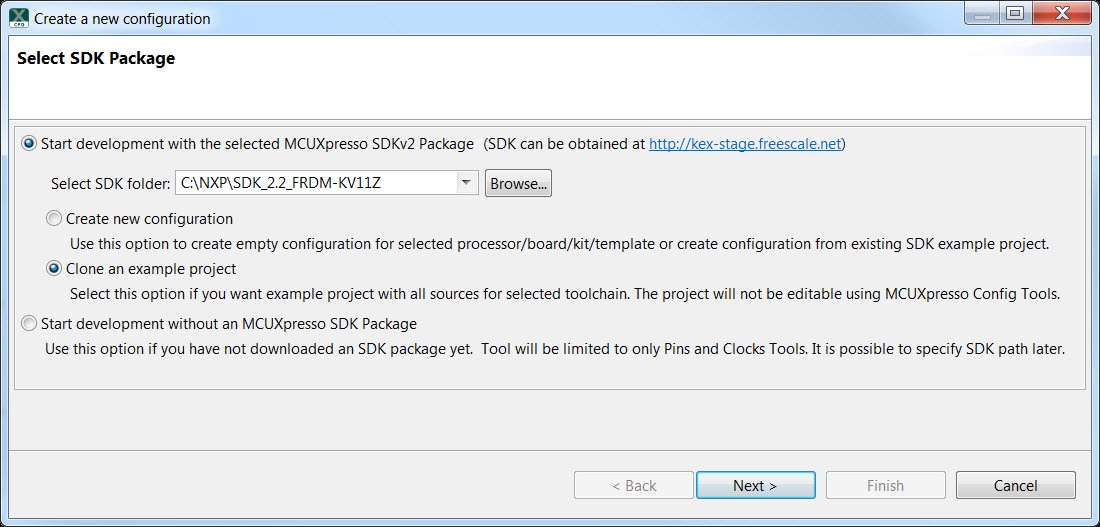
- Open the MCUXpresso Config Tools
- In the wizard that comes up, browse to the place where the
MCUXpresso SDK
was unzipped, and then select the "Clone an example
project"
radio button and click Next
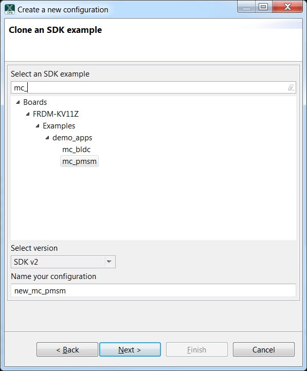
- Select the project to clone. For this example we want to use the LED
project. You can filter for this by typing "mc_" in the
filter
box and then selecting the "demo_apps\mc_pmsm" project.
You can
name your new configuration then click Next
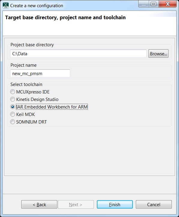
- Then, select the directory you want to place the cloned project, give
it a
name, and select the IDE to use. Note that only IDEs that were
selected in
the online SDK builder when the SDK was built will be available.
Then, click
on Finish
- After cloning go to the directory you selected and open up the project for your IDE and Import the project
For clones of the project mc_pmsm open the project option:
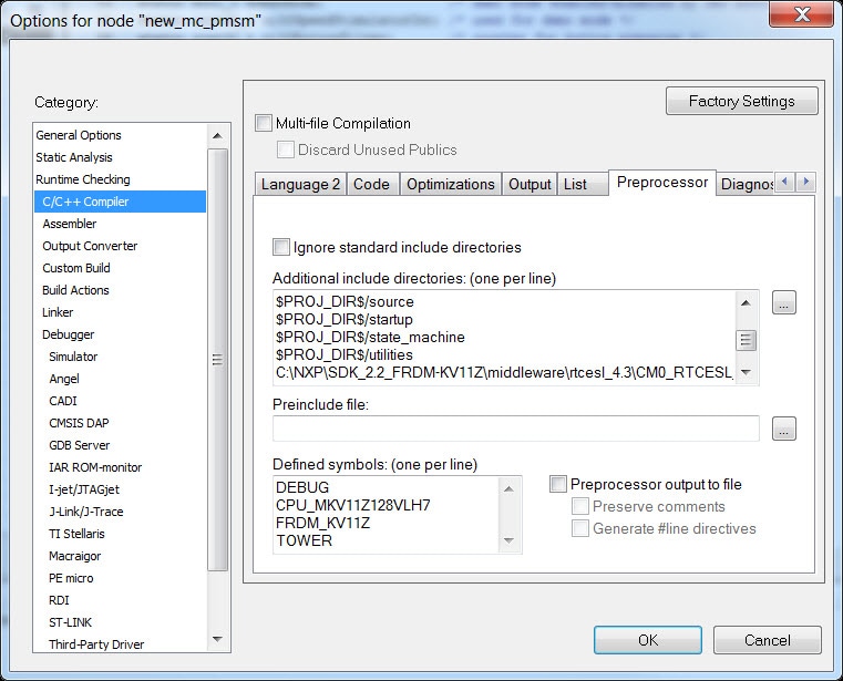
Add the following include directories into the list under the Preprocessor Tab
C:\NXP\SDK_2.2_FRDM-KV11Z\middleware\rtcesl_4.3\CM0_RTCESL_4.3_IAR\GFLIB\Include\C:\NXP\SDK_2.2_FRDM-KV11Z\middleware\rtcesl_4.3\CM0_RTCESL_4.3_IAR\GMCLIB\Include\C:\NXP\SDK_2.2_FRDM-KV11Z\middleware\rtcesl_4.3\CM0_RTCESL_4.3_IAR\GDFLIB\Include\C:\NXP\SDK_2.2_FRDM-KV11Z\middleware\rtcesl_4.3\CM0_RTCESL_4.3_IAR\AMCLIB\Include\C:\NXP\SDK_2.2_FRDM-KV11Z\middleware\rtcesl_4.3\CM0_RTCESL_4.3_IAR\MLIB\Include\
- Compile, and run the project
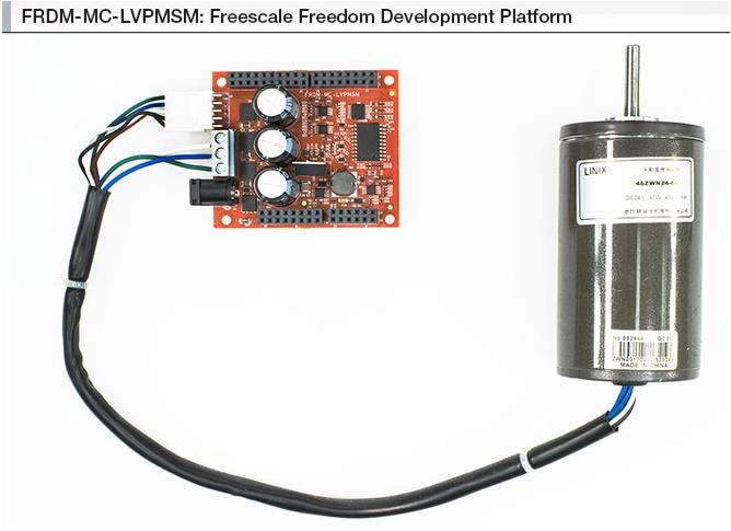
- Make sure the FRDM-KV11Z board is connected to a FRDM-MC-PMSM, a
power
supply and a motor
- After downloading, press
SW2on the FRDM-KV11Z board to start the motor spinning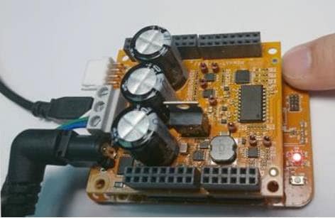
- After the demo stops terminate the debug session
4.2 Use the Pins Tool
Now, let's use the Pins Tool that is part of the MCUXpresso Config Tools to show how to add a new GPIO pin to your project to blink an LED.
Use Pins Tool
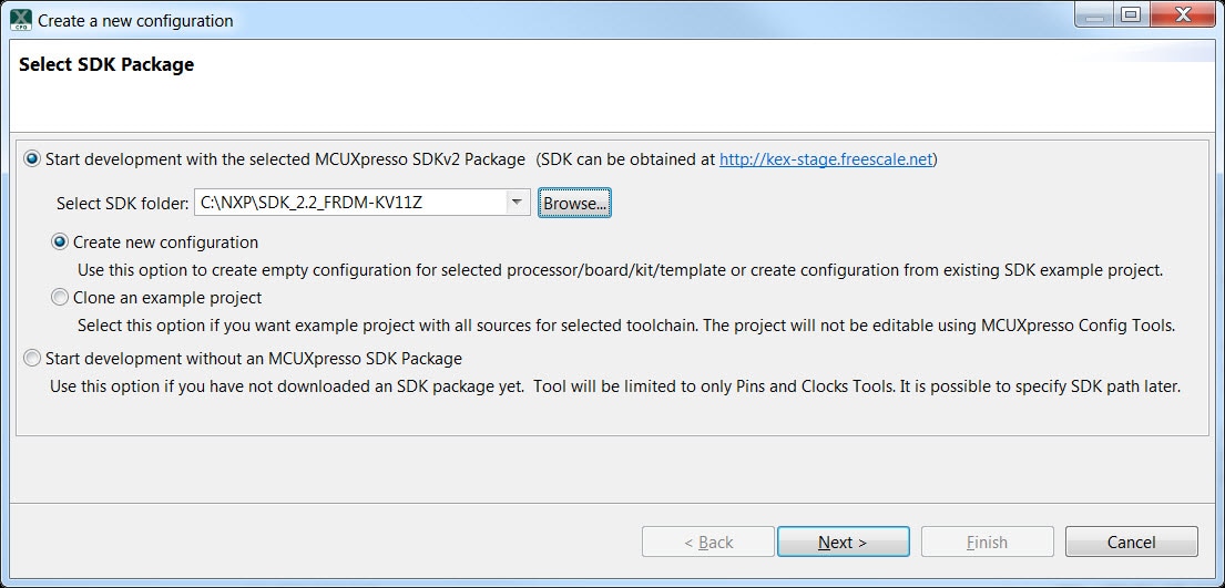
- Open MCUXpresso Config Tools
- The wizard will ask if you want to start development with or without
an SDK.
Choose to start development with the SDK and that we want to create
a new
configuration. Use the "Browse..." button to
navigate to
the location of your unzipped SDK installation
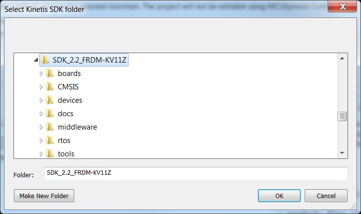
- Select the SDK top-level folder from your file system. Select OK
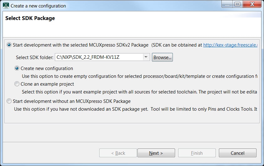
- The wizard asks to create a new configuration or clone an example
project.
We will Create a new configuration that will be based on the
"led_output" project settings from the SDK. Select Next
to
continue
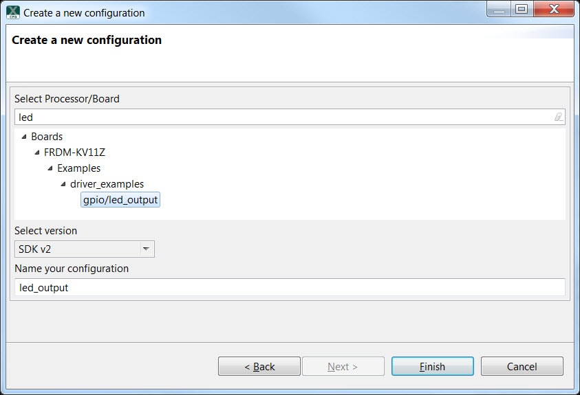
- Search for the led_output example by typing 'led' in the
search
bar. Select the led_output example and press Finish
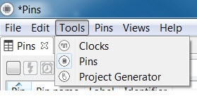
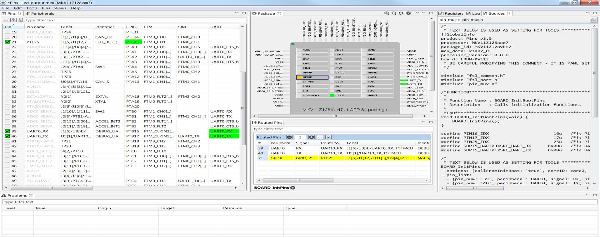
- Open the Pins Tool by selecting Tools → Pins from the toolbar
- The Pins Tool should now display the pin configuration for the
led_output
project
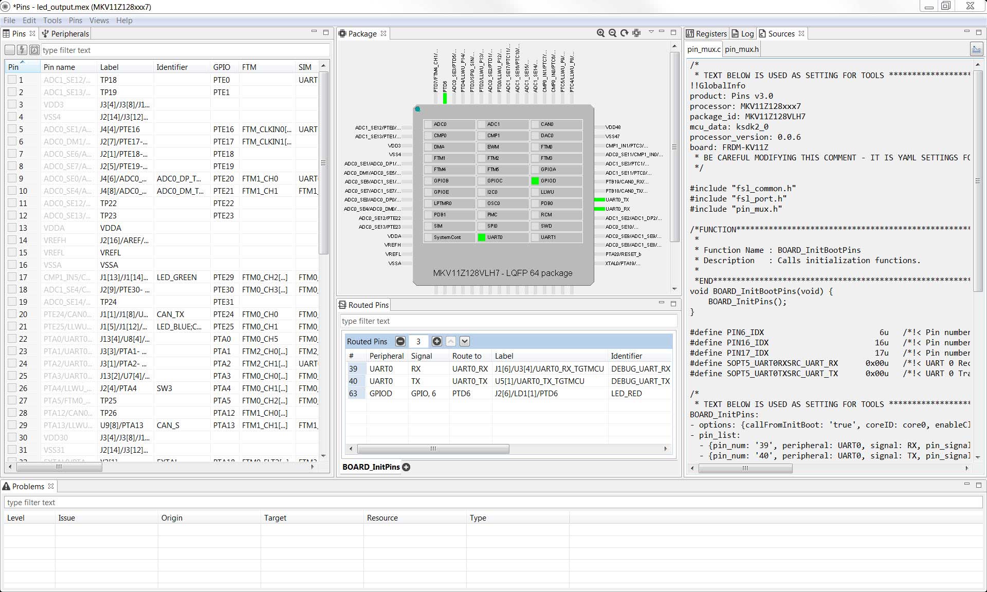
- In the Pins view click the "Show Routed/All Pins"
checkbox to
see all the routed pins. Routed pins have a check in a green box
next to the
pin name. The functions selected for each routed pin are highlighted
in
green in the table

- In the current configuration,
PTD6is routed as a GPIO to toggle the red LED. Let's disablePTD6, and change the mux setting ofPTE25to use its GPIO functionality to drive the blue LED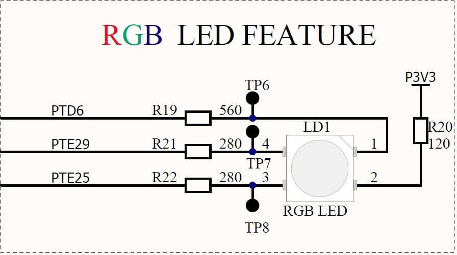
- Disable
PTD6(red LED) as a GPIO by clicking thePTD6field under the GPIO column. The pin will then be disabled (pin will no longer have check in box) and thus disappear from the list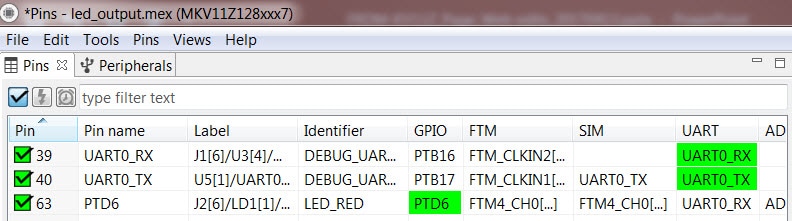
- Now, route
PTE25as a GPIO. First, deselect the "Show Routed All/Pins" so that all the pins are displayed again. Then, search LED_BLUE in the Pins View. Finally, click the box under the GPIO column. The box will highlight in green, and a check will appear next to the pin
- The updated view will appear as below once you clear the filtered
text. Note
that
PTB21also appears in the Routed Pins tab andPTB22has been removed. The pin_mux.c file has been updated to reflect the change as well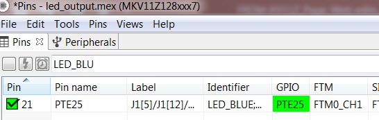
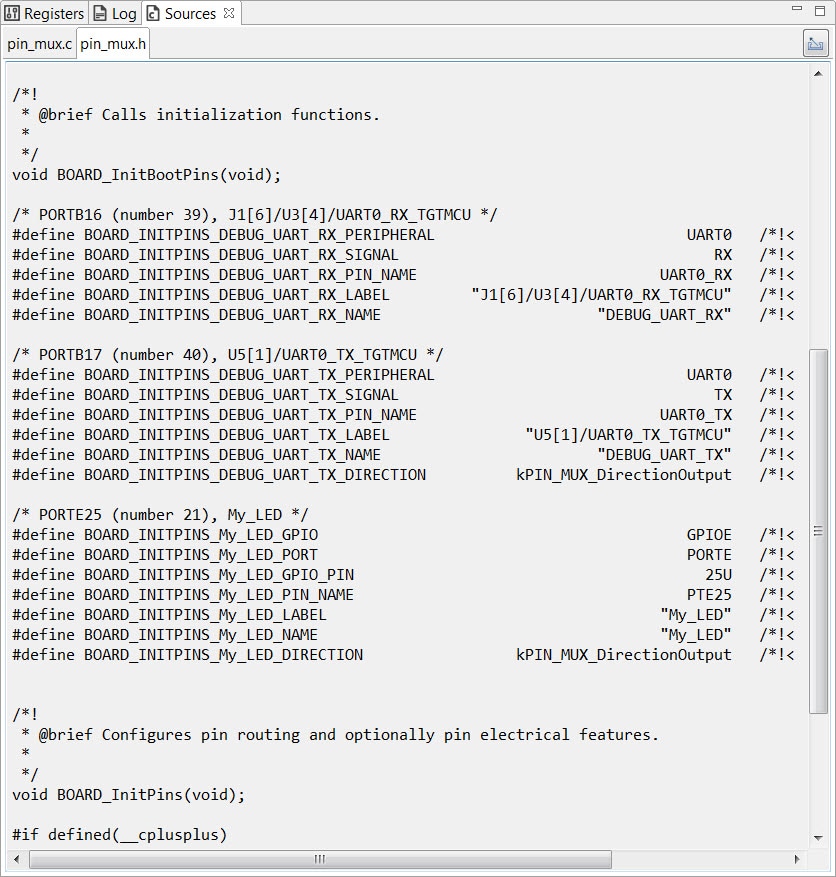
PTE25already has a defined identifier (i.e. LED_BLUE) set up for the FRDM-KV11Z for the led_output example configuration. Now, change the identifier to "My_LED" next toPTE25in the Pins table by searching forPTE25. This will add a #define to the pin_mux.h file that will be used to identify the LED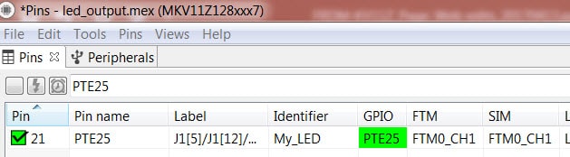
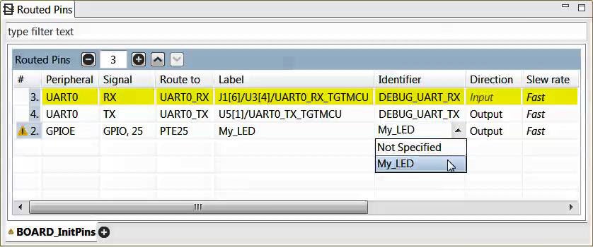
- Now, to complete the labeling go to the Routed Pins frame

- Select the "Not Specified" and from the drop-down
options,
choose the Identifier you just created "My_LED"
- Now, export the pin_mux.c and pin_mux.h files by clicking on the
Sources tab
on the right side to get to the Sources view, and selecting the
export icon
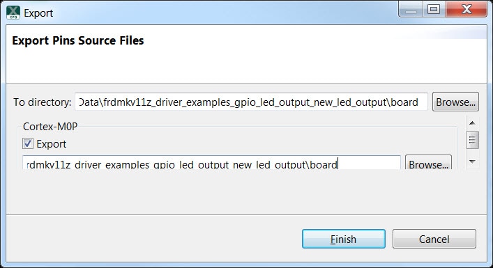
Select the directory to export the pin_mux.c and pin_mux.h files. In this example export to the "board" folder in the led_output project in the workspace that was created in the previous section (i.e.
C:\Data\frdmkv11z_driver_examples_gpio_led_output_new_led_output\board)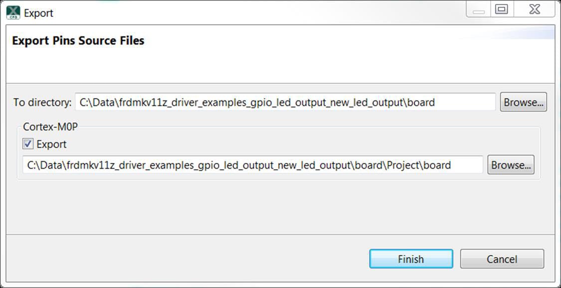
If needed remove the extra text "Project\board" from the Export folder. Select Finish
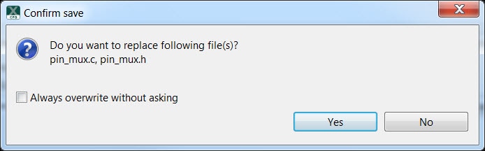
- Click Yes to replace the existing pin_mux.c and pin_mux.h files
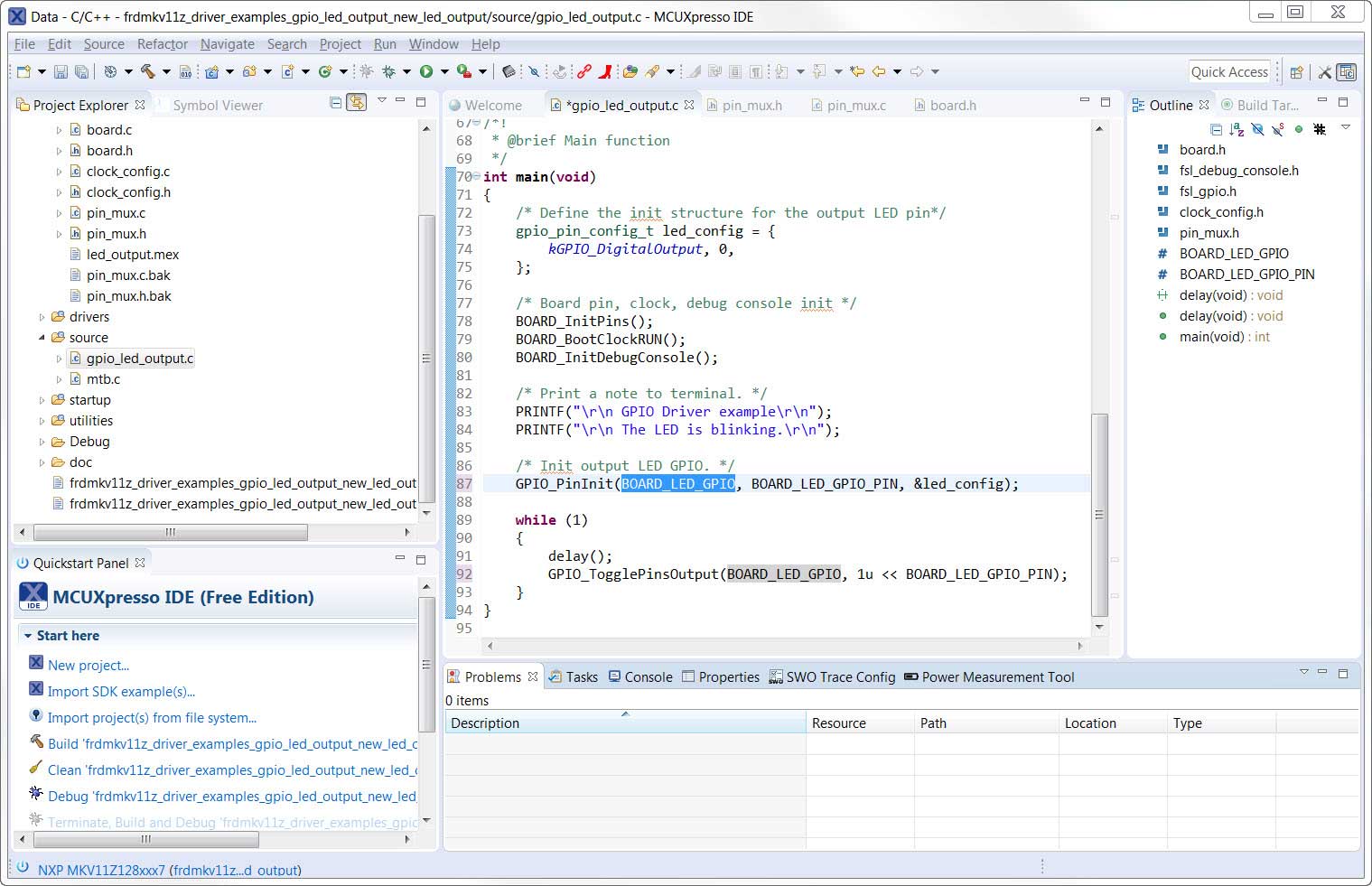
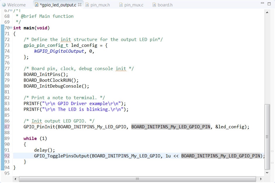
- We'll use MCUXpresso IDE for the rest of the instructions but
the same
steps can be done in other 3rd party IDEs. Under the
"led_output" project, double-click the gpio_led_output.c
file in
the source folder to display the file in the editor. Notice that the
macros
used in the GPIO driver functions refer to the BOARD_LED (i.e. red
LED). We
need to replace these with the macros for My_LED that we just
created
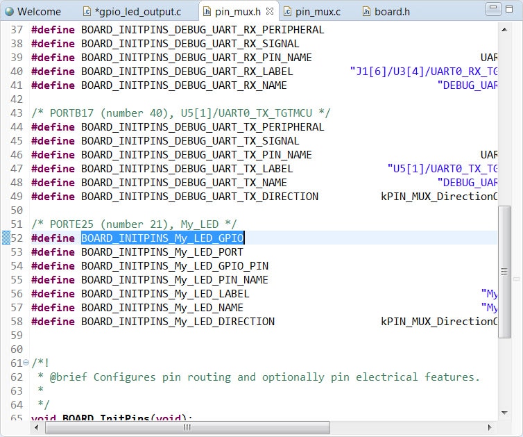
- Double-click the pin_mux.h file under the board folder in the
"led_output" project. Since the file has been updated,
press
"F5" or File → Refresh to update the file in the
editor. Copy
"BOARD_INITPINS_My_LED_GPIO" in pin_mux.h
- In gpio_led_output.c Replace "BOARD_LED_GPIO" with
"BOARD_INITPINS_My_LED_GPIO"
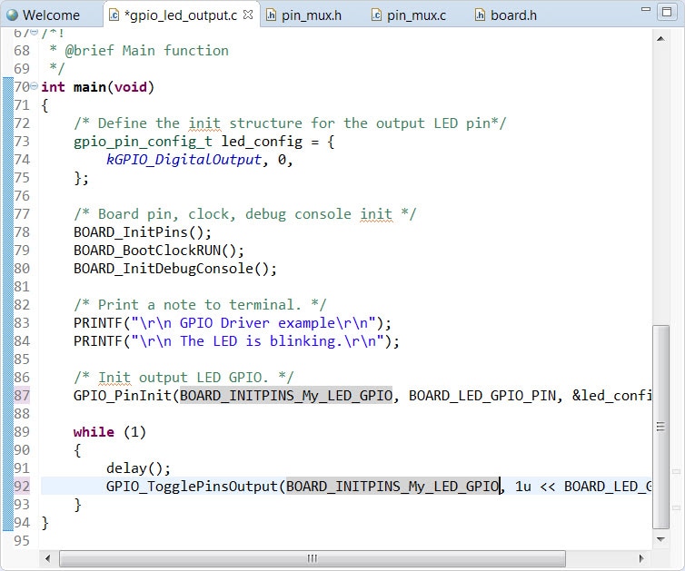
- Similarly, copy "BOARD_INITPINS_My_LED_GPIO_PIN" from
pin_mux.h
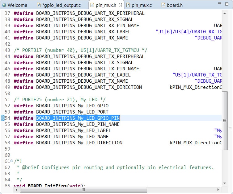
- In gpio_led_output.c replace "BOARD_LED_GPIO_PIN" with
"BOARD_INITPINS_My_LED_GPIO_PIN"
- Build and download the project as done in the previous section
- Run the application. You should now see the blue LED blinking!
- Terminate the debug session
4.3 Use the Clocks Tool
Next use the Clocks Tool that is part of the MCUXpresso Config Tools to change the clock settings and change the rate that the LED blinks.
Use the Clocks Tool
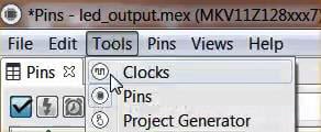
- Open MCUXpresso Config Tools if it is not open already
- Open the Clocks Tool from the toolbar: Tools → Clocks
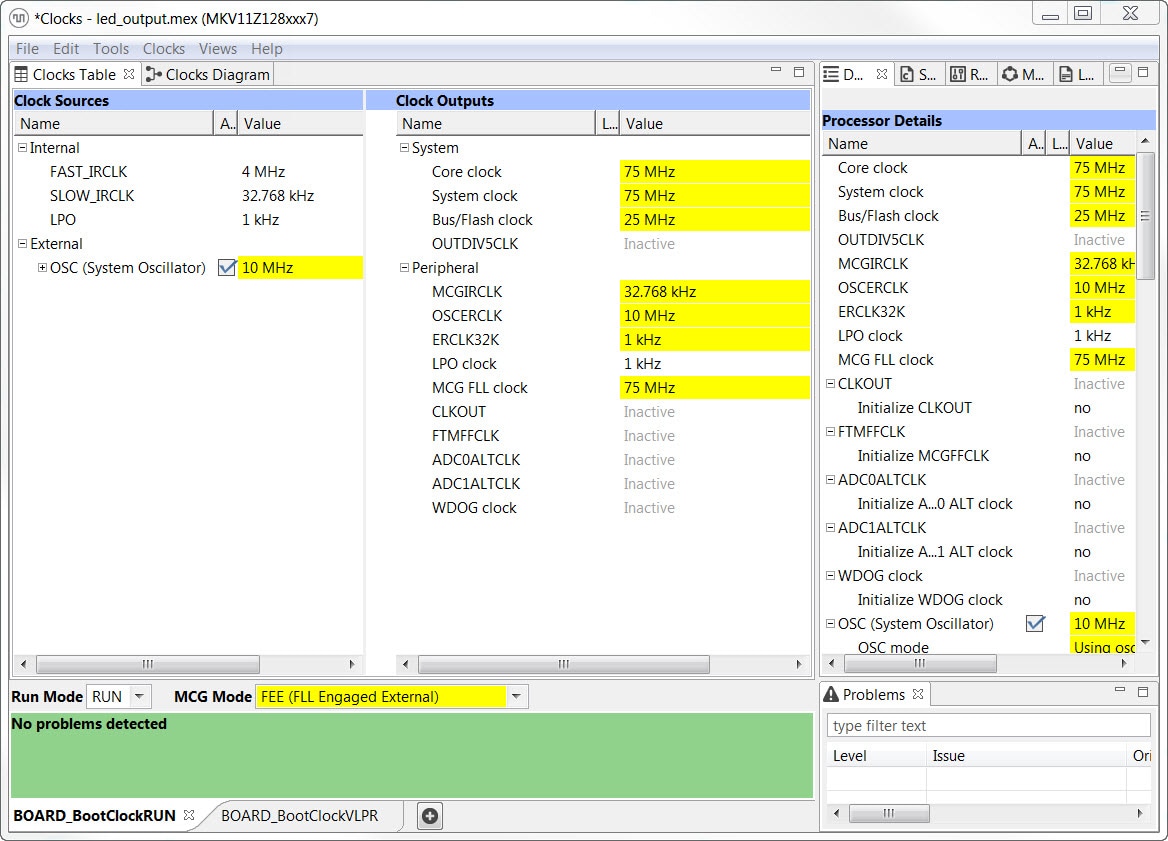
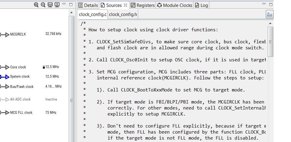
- The clock configuration for the 'led_output' project
will appear
in the Clocks Tool:
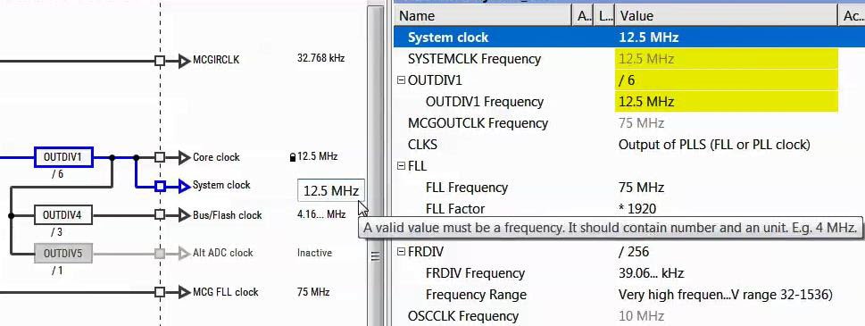
- Switch to the Clocks Diagram view by clicking the tab in the upper
left
corner, and ensure that the BOARD_BootClockRUN clock mode is being
displayed
by clicking the tab in the lower left corner

- Change the core clock frequency by clicking in the Core Clock field
and
typing "12.5 MHz". You'll see all the associated
clock
frequencies automatically change as well then
- Now open the "Sources" tab and export the clock_config.c
and
clock_config.h files
-
Select the directory to export the clock_config.c and
clock_config.h
files. In this example export to the 'board' folder
in the
led_output project in the workspace. (i.e.
C:\MCUXpressoIDE_Lab\frdmkv11z_driver_examples_gpio_led_output\board). Remove the text "\Project\board" then select Finish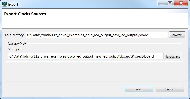
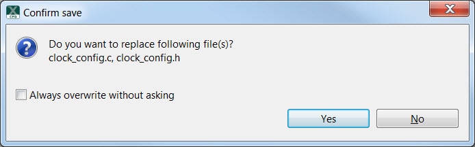
- Press Yes to replace the existing clock_config.c and clock_config.h
files
- Now, open the led project in your IDE, and build, download, and run the project as you did before
- The blue LED should now be blinking at a much slower rate
4.4 Success
With the application modified, you will see the FRDM-KV11Z's blue LED slowly blinking. You can also view the terminal output using the terminal program.
Tera Term Tutorial
Tera Term Tutorial
Tera Term is a very popular open source terminal emulation application. This program can be used to display information sent from your NXP development platform's virtual serial port.
- Download Tera Term from SourceForge. After the download, run the installer and then return to this webpage to continue
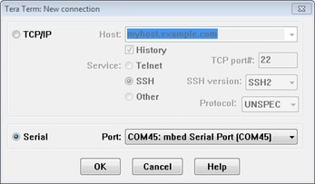
- Launch Tera Term. The first time it launches, it will show you the following dialog. Select the Serial option. Assuming your board is plugged in, there should be a COM port automatically populated in the list
- Configure the serial port settings (using the COM port number identified earlier) to 115,200 baud rate, 8 data bits, no parity and 1 stop bit. To do this, go to Setup → Serial Port and change the settings
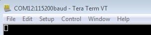
- Verify that the connection is open. If connected, Tera Term will show something like below in its title bar
- You're ready to go
PuTTY Tutorial
PuTTY Tutorial
PuTTY is a popular terminal emulation application. This program can be used to display information sent from your NXP development platform's virtual serial port.
- Download PuTTY using the button below. After the download, run the installer and then return to this webpage to continue
- Launch PuTTY by either double clicking on the *.exe file you downloaded or from the Start menu, depending on the type of download you selected
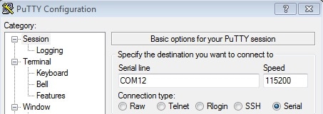
- Configure in the window that launches, select the Serial radio button and enter the COM port number that you determined earlier. Also enter the baud rate, in this case 115,200
- Click Open to open the serial connection. Assuming the board is connected, and you entered the correct COM port, the terminal window will open. If the configuration is not correct, PuTTY will alert you
- You're ready to go
Design Resources
Board Information
Chip Documents
Software
Additional Resources
Explore beyond the FRDM-KV11Z by adding other NXP solutions to your project and interact with our worldwide design community.
Sensors
Explore the world with a full assortment of NXP sensor solutions. From accelerometers, pressure sensors, touch sensors and many more, NXP has a sensor solution for your project. Find out more at Sensors.
NFC
Near Field Communication is a simple, intuitive technology that lets you interact securely with the world around you with a simple touch. Learn more about NXP's NFC solutions at NFC - Near Field Communication.
Support
Troubleshooting
Did your board come in a box that looks like this?

No problem! Your board simply came in the old packaging and has a different out-of-box demo loaded into the flash memory.
You should be seeing the red and green LEDs toggling back and forth. It's OK to move onto the next step when you're ready.
Still not working?
Try proceeding to the next steps to get other example applications running on your board. If you still have problems, try contacting us through the NXP Community .
Forums
Connect with other engineers and get expert advice on designing with Kinetis MCUs and MCUXpresso Software and Tools. Go to Support or join the community discussion in one of our two dedicated communities: