Getting Started with the FRDM-PF1510EVM
Contents of this document
-
Get Started
-
Know the Board
-
Configure Hardware
-
Install Software
Sign in to save your progress. Don't have an account? Create one.
Purchase your PF1510 for Low Power Application Processors
1. Get Started
The NXP analog product development boards provide an easy-to-use platform for evaluating NXP products. The boards support a range of analog, mixed-signal and power solutions. They incorporate monolithic integrated circuits and system-in-package devices that use proven high-volume technology. NXP products offer longer battery life, a smaller form factor, reduced component counts, lower cost and improved performance in powering state-of-the-art systems.
This page will guide you through learning about how to set up the FRDM-PF1510EVM board.
1.1 Kit Contents/Packing List
The FRDM-PF1510EVM contents include:
- Assembled and tested evaluation board in an anti-static bag
- Cable, USB type A male/type mini B male 3 ft
- Quick start guide
1.2 Required Equipment
This kit requires the following items:
- 5.0 V DC power supply or USB with enough current capability (3.0 A for maximum performance)
- KITPF1510GUI installed on a Windows PC
- Optional voltmeters to measure regulator outputs
- Optional oscilloscope
- 2x Mini USB Cables
1.3 System Requirements
The kit requires the following to function properly with the software:
- USB-enabled computer running Windows XP, Vista 7, 8, or 10 (32-bit or 64-bit)
2. Know the Board
2.1 Board Features
- PF1510 PMIC
- Integrated FRDM-KL25Z as a communication link between the EVB and a PC
| Device | Description | Features |
|---|---|---|
| PF1510 | Power management integrated circuit (PMIC) for i.MX 7ULP, 6SL, 6UL, 6ULL, and 6SX processors |
|
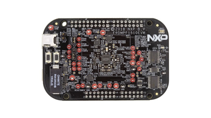
2.2 Board Description
The FRDM-PF1510EVM boards serve as an evaluation platform that allows users to test and demo designs that incorporate the PF1510 PMIC. The evaluation board contains a pre-configured MC32PF1510A4EP device and provides numerous jumpers and test points that allow users to tailor the evaluation to their needs. The kit comes with an FRDM-KL25Z already mounted and loaded with compatible microcode. The primary function of the FRDM-KL25Z is to control communication between the evaluation board and a PC.
3. Configure Hardware
3.1 Configuration Hardware
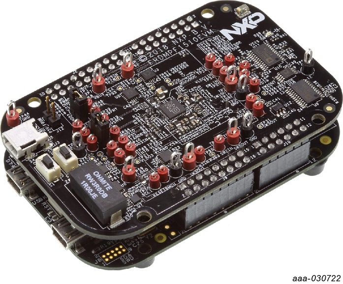
The FRDM-KL25Z evaluation board was chosen specifically to work with the FRDM-PF1510EVM kit because of its low cost and features. The FRDM-KL25Z board uses the USB, built-in LEDs, and I/O ports available with NXPs Kinetis KL2x family of microcontrollers.
The FRDM-PF1510EVM connects to the FRDM-KL25Z using the four-dual row Arduino R3 connectors on the bottom of the board.
Suggested equipment's needed for test:
- 5.0 V power supply
- Computer
- 2x Mini USB Cables
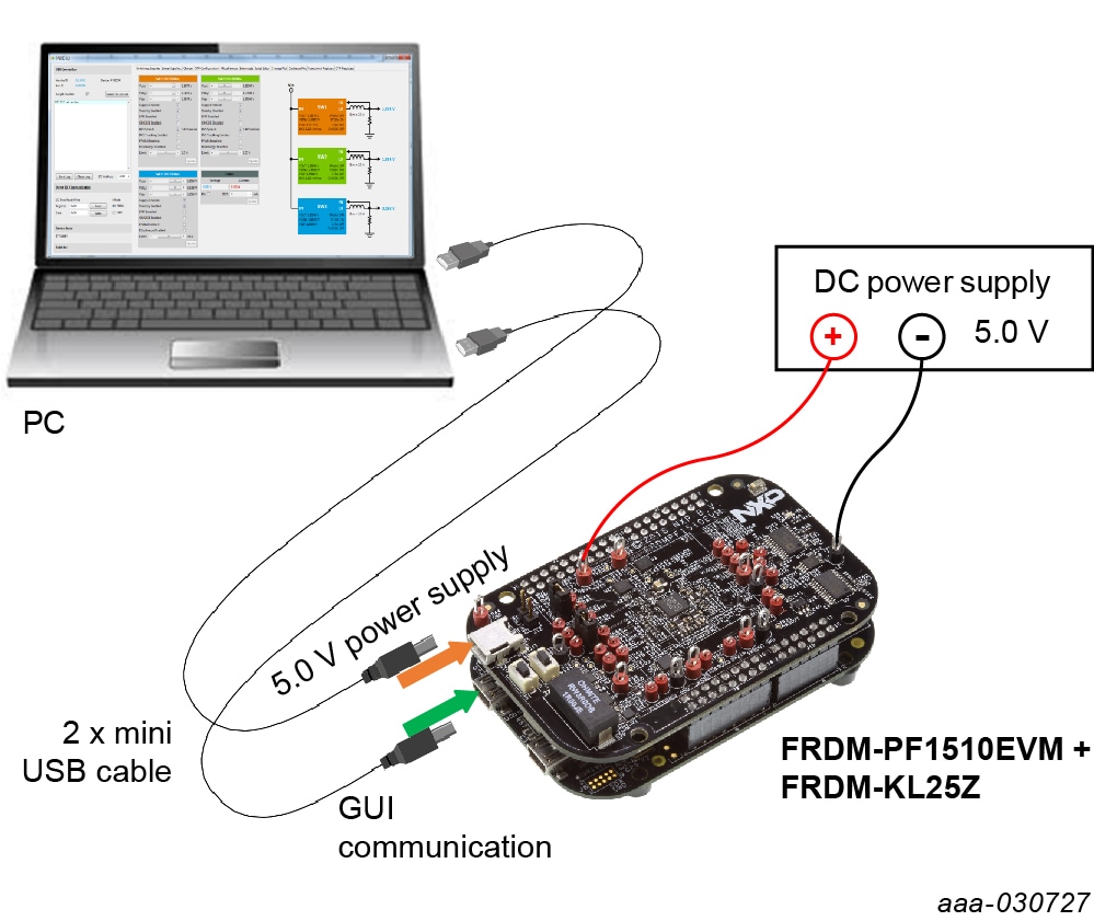
3.3 Connect USB Cable
Connect the mini-USB cable from a PC to the KL25Z USB port on the FRDM-KL25Z board. Connect the other end of the cable to a host computer.
4. Install Software
4.1 Graphical User Interface
Download and run SW for the FRDM-PF1510EVM with the next step.
4.2 Set Up PF1510GUI on your Computer
- Download PF1510 GUI for 32-bit or PF1510 GUI for 64-bit. Choose the 32-bit or 64-bit version regarding the system installed on your PC
- Extract all the files to any desired folder on your PC
- Plug the evaluation board
- Launch the GUI (no installation is necessary, GUI can be directly launched by clicking the file
PF1510_x_Bx.jar) - Configure the hardware
- Launch the PF1510 GUI
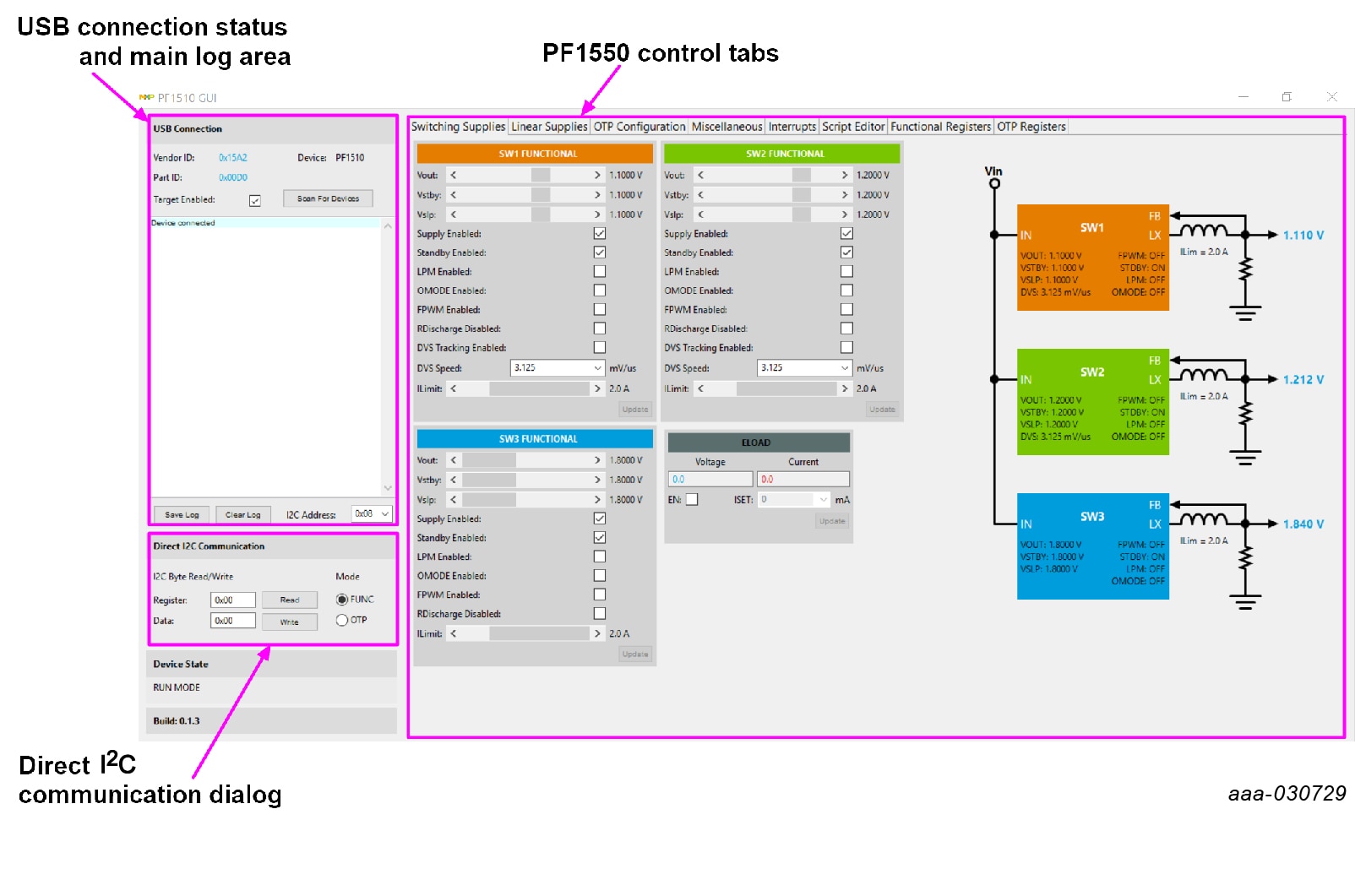
Main log window indicate a connection.
Design Resources
Board Documents
Chip Documents
Software
Additional Resources
Product Summary Page
For PF1510 is located at PF1510.
Tool Summary Page
The overview tab provides an overview of the device, product features, a description of the kit contents, a list of (and links to) supported devices, list of (and links to) any related products and a Get Started section.
- On the Overview tab, locate the Jump To navigation feature on the left side of the window
- Select the Get Started link, review each entry and download an entry by clicking on the title
-
After reviewing the Overview tab, visit the other product-related tabs for additional information:
- Documentation: download current documentation
- Software and Tools: download current hardware and software tools / Drivers
- Buy/Parametrics: purchase the product and view the product parametric. After downloading files, review each file, including the user guide which includes setup instructions
- Build a package: the bill of materials (BOM) and supporting schematics are also available for download in the Get Started section of the Overview tab
For the Entire Solution
In addition to our PF1510 Power Management Integrated Circuit (PMIC) for low power application processors page you may also want to visit:
Product Pages
- i.MX7ULP: i.MX 7ULP Family: Ultra-Low-Power with Graphics
- i.MX6ULL: i.MX 6ULL Single-Core Processor with Arm® CortexV-A7 Core
- i.MX6UL: i.MX 6UltraLite Processor - Low-power, secure, Arm® Cortex®-A7 Core
- FRDM-KL25Z: FRDM Development Platform for Kinetis® KL14, KL15, KL24, KL25 MCUs
Application Pages
Hardware Pages
Software Pages
Support
Forums
Connect with other engineers and get expert advice on designing with the FRDM-PF1510EVM on our community site.