Getting Started with the MCIMX7SABRE
Contents of this document
-
Out of the Box
-
Embedded Linux®
-
Embedded Android™
-
FreeRTOS™
-
Explore
Sign in to save your progress. Don't have an account? Create one.
Purchase your i.MX 7Dual SABRE Board
1. Out of the Box
The following section describes the steps to boot the i.MX7Dual Sabre.
Development Kit Contains:
- i.MX7Dual Sabre board for smart devices
- USB cable (micro-B to standard-A)
- Cable -Assembly, USB 3.0 Type-A Male, USB micro-B Male, Shielded, 1m
- 5V/5A universal power supply
- Quick Start Guide
- 8 GB SD Card with bootable operating system demonstration image
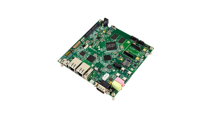
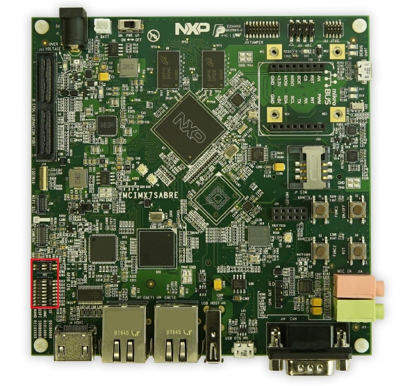
1.1 Get Familiar with the Board
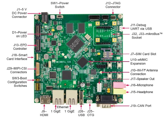
Figure 1. i.MX7Dual Sabre front
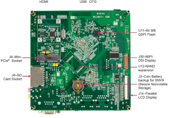
Figure 2. i.MX7Dual Sabre back
1.2 Insert the SD Card (SD1/J6)
The kit includes an SD card with a pre-built NXP Linux binary demo image. Without modifying the binary inside the SD card, booting from this SD card provides a default system with certain features for building other applications on top of Linux. The software is described in the following sections.
1.3 Connect USB Debug Cable
Connect the micro-B end of the supplied USB cable into Debug UART port J11. Connect the other end of the cable to a host
computer.
If you are not sure about how to use a terminal application, try one of the following tutorials depending on the operating system of the host machine:
Tera Term Tutorial, PuTTY Tutorial, Minicom Tutorial.1.4 Connect the HDMI cable
To see the user interface provided with the SD card image binary connect a monitor via the HDMI connector
(J9).
1.6 Connect Power Supply
Connect the 5V power supply cable to the 5V DC power jack (J1).
Power the board by flipping the switch (SW1). The
processor starts executing from the on-chip ROM code. With the default boot switch setup, the code reads
the fuses to define the media where it is expected to have a bootable image. After it finds a bootable
image on the SD card, the U-Boot execution should begin automatically.
Information is printed in the smaller number serial console for the Cortex-A7 (COM9 on Windows as an example and /dev/ttyUSB* on Linux). If you don not stop the U-Boot
process, it continues to boot the Linux kernel.
On Windows as an example
1.7 Congratulations Linux® has booted
Once Linux is booted, login using the user name root
and no password.
Tip: To proceed to U-Boot, press any key before the value of the U-Boot environment
variable, bootdelay, decreases and before it times out
(default 3 seconds). If you stop the U-Boot process, you can run the following command to continue with
the Linux boot process:
# boot2. Embedded Linux®
This section is applicable ONLY if attempting to load a Linux operating system on the board.
The i.MX Linux Board Support Package (BSP) is a collection of binary files, source code, and support files that are used to boot an Embedded Linux image on a specific i.MX development platform.
Current releases of Linux binary demo files can be found on the i.MX Linux download page. The Linux User Guide and Linux Reference Manual provide additional information. Additional documentation can be found the i.MX Linux documentation bundle, or under the Linux sections on the i.MX Software and Development Tool.
2.1 Overview
Before the Linux OS kernel can boot on an i.MX board, the Linux image is copied to a boot device (SD card, eMMC and so on) and the boot switches are set to boot that device.
There are various ways to download the Linux BSP image for different boards and boot devices.
For this getting started guide, only a few methods to transfer the Linux BSP image to an SD card are listed. Experienced Linux developers can explore other options.
2.2 Download an NXP Linux BSP pre-built image
The latest pre-built images for the i.MX 8QuadMax MEK are available on the Linux download page. The file L4.14.78_1.0.0_ga_images_MX7DSABRESD.zip gathers every artifact required to boot the board.
The pre-built NXP Linux binary demo image provides a typical system and basic set of features for using and evaluating the processor. Without modifying the system, the users can evaluate hardware interfaces, test SoC features, and run user space applications.
When more flexibility is desired, an SD card can be loaded with individual components (boot loader, kernel, dtb file, and rootfs file) one-by-one or the .sdcard image is loaded and the individual parts are overwritten with the specific components.
2.3 Burn NXP Linux BSP image using UUU
In addition to the connections from Out of box chapter, connect the J25 to the host machine using the proper USB cable.
Turn off the board. Consult Boot switch setup and configure the board to boot on SDP (Serial Download Protocol) mode.
Depending on the OS used in the host machine, the way to transfer the Linux BSP image onto an SD card can vary.
Choose an option below for detailed instructions:
Linux®
1. Install UUU on Linux Distro
Download the latest stable files from UUU GitHub page. An extensive tutorial for UUU can be found in mfgtools.
- uuu
- libusb1 (via apt-get or any other package manager)
2. Burn the NXP Linux BSP image to the board
By default, this procedure flashes the image to the SD card flash. Check the UUU GitHub page for reference on how to flash the image to other devices.
Open a terminal application and change directory to the location where uuu and the latest Linux distribution for i.MX7Dual Sabre are located. Add execution permission to the uuu file and execute it. Uuu waits for the USB device to connect
$ chmod a+x uuu
$ sudo ./uuu L4.14.78_1.0.0_ga_images_MX7DSABRESD.zip
Turn on the board, uuu starts to copy the images to the board.
When it finishes, turn off the board, and consult Boot switch setup to configure the board to boot from SD card.
Windows™
1. Install UUU on Linux Distro
Download the latest stable files from UUU GitHub page. An extensive tutorial for UUU can be found in mfgtools.
- uuu
- libusb1 (via apt-get or any other package manager)
2. Burn the NXP Linux BSP image to the board
By default, this procedure flashes the image to the SD card flash. Check the UUU GitHub page for reference on how to flash the image to other devices.
Open a terminal application and change directory to the location where uuu and the latest Linux distribution for i.MX7Dual Sabre are located. Add execution permission to the uuu file and execute it. Uuu waits for the USB device to connect
$ chmod a+x uuu
$ sudo ./uuu L4.14.78_1.0.0_ga_images_MX7DSABRESD.zip
Turn on the board, uuu starts to copy the images to the board.
When it finishes, turn off the board, and consult Boot switch setup to configure the board to boot from SD card.
3. Embedded Android™
This section describes the boot process of loading the i.MX7Dual Sabre board with an Embedded Android system image and introduces how to build the software components that create your own system image. For details on building the Android platform, see https://source.android.com/source/building.html
The current release includes Demo Images, Source code and Documentation. These can also be found under Android section of the i.MX Software and Development Tool.
3.1 Overview
The storage devices on the development system (MMC/SD or NAND) must be programmed with the U-Boot boot loader. The boot process determines which storage device to access based on the switch settings. When the boot loader is loaded and begins execution, the U-Boot environment space is then read to determine how to proceed with the boot process.
The images can come from pre-built release packages or be created from source code. Regardless of how you obtain them, all Android images contain the following components:
-
U-Boot image:
u-boot.imx -
boot image:
boot.img -
Android system root image:
system.img -
Recovery root image:
recovery.img
For more information about the Android BSP refer to the Android User Guide.
Depending on the OS used in the host machine, the way to transfer the Android BSP image onto an SD card can vary.
3.2 Download NXP Android BSP image
The pre-built NXP Android demo image provides a default system with certain features for evaluation. Without modifying the system, users can perform some basic operations, and interact with the system to test hardware interfaces and develop software application in the user space.
The pre-built images from the package are categorized by boot device and put in the directory with the device name. The latest pre-built image files can be found in Android section on the i.MX Software and Development Tool, or on the demo images downloader link.
Burn NXP Android BSP image using UUU
In addition to the connections from Out of box chapter, connect the J25 to the host machine using the proper USB cable.
Turn off the board. Consult Boot switch setup and configure the board to boot on SDP (Serial Download Protocol) mode.
Depending on the OS used in the host machine, the way to transfer the Linux BSP image onto an SD card can vary.
Choose an option below for detailed instructions:
Linux®
1. Install UUU on Linux Distro
Download the latest stable files from UUU GitHub page. An extensive tutorial for UUU can be found in mfgtools.
- uuu
- libusb1 (via apt-get or any other package manager)
2. Burn the NXP Linux BSP image to the board
By default, this procedure flashes the image to the SD card flash. Check the UUU GitHub page for reference on how to flash the image to other devices.
Open a terminal application and change directory to the location where uuu and the latest Linux distribution for i.MX7Dual Sabre are located. Add execution permission to the uuu file and execute it. Uuu waits for the USB device to connect
$ chmod a+x uuu
$ sudo ./uuu L4.14.78_1.0.0_ga_images_MX7DSABRESD.zip
Turn on the board, uuu starts to copy the images to the board.
When it finishes, turn off the board, and consult Boot switch setup to configure the board to boot from SD card.
Windows™
1. Install UUU on Linux Distro
Download the latest stable files from UUU GitHub page. An extensive tutorial for UUU can be found in mfgtools.
- uuu
- libusb1 (via apt-get or any other package manager)
2. Burn the NXP Linux BSP image to the board
By default, this procedure flashes the image to the SD card flash. Check the UUU GitHub page for reference on how to flash the image to other devices.
Open a terminal application and change directory to the location where uuu and the latest Linux distribution for i.MX7Dual Sabre are located. Add execution permission to the uuu file and execute it. Uuu waits for the USB device to connect
$ chmod a+x uuu
$ sudo ./uuu L4.14.78_1.0.0_ga_images_MX7DSABRESD.zip
Turn on the board, uuu starts to copy the images to the board.
When it finishes, turn off the board, and consult Boot switch setup to configure the board to boot from SD card.
4. FreeRTOS™
This section describes how to load FreeRTOS for i.MX7Dual. FreeRTOS is an optional Real-Time Operating System (RTOS) which NXP uses to enable the Cortex-M cores in some of our products. Enabling the Cortex-M cores is an optional step. If you do not wish to enable the Cortex-M4 on i.MX7Dual at this moment you can skip this section.
The FreeRTOS BSP for i.MX7Dual is a suite of robust peripheral drivers and multicore communication mechanism designed to simplify and accelerate application development on the i.MX7Dual Processor.
Included in the FreeRTOS BSP for i.MX7Dual is full source code under a permissive open-source license for all demos, examples, middleware, and peripheral driver software.
4.1 Overview
The FreeRTOS BSP for i.MX7Dual consists of the following runtime software components written in C:
- Arm® Cortex Microcontroller Software Interface Standard (CMSIS) Core, DSP standard libraries, and CMSIS-compliant device header files which provide direct access to the peripheral registers and bits.
- A set of peripheral drivers that provides a simple, stateless driver with an API encapsulating register access of the peripheral.
- A multicore communication mechanism (RPMsg) to decrease the developing difficulty of multicore communication.
- A FreeRTOS operating system to provide an event triggered preemptive scheduling RTOS.
The demos/examples in FreeRTOS BSP are built for on-chip Tightly Coupled Memory (TCM) in the Arm® Cortex®-M4® core.
4.2 Download NXP FreeRTOS source and demos
Current releases of the NXP FreeRTOS BSP and source code can be found on the links below. There is option to download a self-extract installer that can be used on Windows OS, or a tarball for installation on Linux OS.
There are four main areas under the install directory of the FreeRTOS BSP tree used to provide the full source code for each demo application:
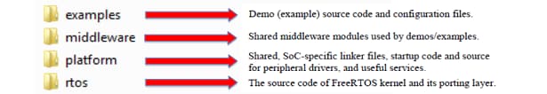
- The
examplesfolder contains all demos/examples source code and board configuration files. All 21 applications are cataloged by board name. - The
middlewarefolder contains the source code of all the middleware used by demos and examples. The open source multicore communication stack – RPMsg is included in the middleware folder. - The
platformfolder contains the source code for the primary components including CMSIS header files, peripheral drivers, startup, utilities, and linker files. - The
rtosfolder contains the source code of market leading RTOS – FreeRTOS OS.
The FreeRTOS BSP comes with rich demo applications and driver examples. To see what’s available,
browse the BSP examples folder and select the
i.MX7Dual Sabre board
(
To learn more about demo applications or driver examples, open the FreeRTOS i.MX7Dual Demo Application
User’s Guide, located in
If one or more of the demo applications or driver examples sounds interesting, you’re probably wanting to know how you can build and debug yourself. The Getting Started Guide with FreeRTOS BSP provides easy, step-by-step instructions on how to configure, build, and debug demos for all toolchains supported by the BSP.
Depending on the OS used in the host machine, the way to build and deploy the demos can vary.
The pre-built NXP Android demo image provides a default system with certain features for evaluation. Without modifying the system, users can perform some basic operations, and interact with the system to test hardware interfaces and develop software application in the user space.
The pre-built images from the package are categorized by boot device and put in the directory with the device name. The latest pre-built image files can be found in Android section on the i.MX Software and Development Tool, or on the demo images downloader link.
Burn NXP Android BSP image using UUU
In addition to the connections from Out of box chapter, connect the J25 to the host machine using the proper USB cable.
Turn off the board. Consult Boot switch setup and configure the board to boot on SDP (Serial Download Protocol) mode.
Depending on the OS used in the host machine, the way to transfer the Linux BSP image onto an SD card can vary.
Choose an option below for detailed instructions:
Linux®
1. Install UUU on Linux Distro
Download the latest stable files from UUU GitHub page. An extensive tutorial for UUU can be found in mfgtools.
- uuu
- libusb1 (via apt-get or any other package manager)
2. Burn the NXP Linux BSP image to the board
By default, this procedure flashes the image to the SD card flash. Check the UUU GitHub page for reference on how to flash the image to other devices.
Open a terminal application and change directory to the location where uuu and the latest Linux distribution for i.MX7Dual Sabre are located. Add execution permission to the uuu file and execute it. Uuu waits for the USB device to connect
$ chmod a+x uuu
$ sudo ./uuu L4.14.78_1.0.0_ga_images_MX7DSABRESD.zip
Turn on the board, uuu starts to copy the images to the board.
When it finishes, turn off the board, and consult Boot switch setup to configure the board to boot from SD card.
Windows™
1. Install UUU on Linux Distro
Download the latest stable files from UUU GitHub page. An extensive tutorial for UUU can be found in mfgtools.
- uuu
- libusb1 (via apt-get or any other package manager)
2. Burn the NXP Linux BSP image to the board
By default, this procedure flashes the image to the SD card flash. Check the UUU GitHub page for reference on how to flash the image to other devices.
Open a terminal application and change directory to the location where uuu and the latest Linux distribution for i.MX7Dual Sabre are located. Add execution permission to the uuu file and execute it. Uuu waits for the USB device to connect
$ chmod a+x uuu
$ sudo ./uuu L4.14.78_1.0.0_ga_images_MX7DSABRESD.zip
Turn on the board, uuu starts to copy the images to the board.
When it finishes, turn off the board, and consult Boot switch setup to configure the board to boot from SD card.
4.3 Run applications using U-Boot
This section describes how to run applications using an SD card using pre-built U-Boot image for i.MX processor.
- Prepare an SD card with a pre-built U-Boot + Linux image from Linux BSP package for the i.MX7Dual processor following the steps on the Embedded Linux® tab. If you have already loaded your SD card with a Linux image you can skip this step.
- Insert the SD card to the your host computer (Linux or Windows), and copy the application image (for
example
hello_world.bin) that you want run to the FAT partition of the SD card. - Safely remove the SD card from the PC.
- Insert the SD card to the target board. Make sure to use the default boot SD slot and double check the Boot Switch Setup. The default configuration of the validation board boots from SD1/J6, and on Sabre board there is only one SD slot which is used for boot.
-
Connect the DEBUG UART slot on the board with your PC through the USB cable. The Windows OS installs the USB driver automatically, and the Ubuntu OS will find the serial devices as well.
See Serial Communication Console setup section in Out of the Box for more instructions for serial communication applications.
- Open a second terminal emulator on the i.MX7Dual Sabre board’s second enumerated serial port.
This is the Cortex-M4’s serial console. Set the speed to
115200bps, data bits8, no parity, and power on the board. -
Power up the board and stop the boot process by pressing any key before the U-boot countdown reaches zero. At the U-Boot prompt on the first terminal emulator, type the following commands to U-Boot.
-
=> fatload mmc 2:1 0x7F8000.bin -
=> dcache flush -
=> bootaux 0x7F8000
-
These commands copy the FreeRTOS memory image file from the first partition of the SD card into the Cortex-M4’s memory and releases the Cortex-M4 from reset.
Some applications with the names ended by ddr or ocram in FreeRTOS BSP should be run in DDR or OCRAM.
Those ended by qspi should boot from external QSPI
flash.
For additional instructions on how to boot from other storage, read section 6.2 and 6.3 in Getting Started with FreeRTOS found inside the package downloaded in section Download NXP FreeRTOS source and demos.
Example Demo
Demo and example applications are provided to demonstrate peripheral drivers, FreeRTOS kernel, RPMsg usage and to highlight the main features of the i.MX7Dual processor.
The FreeRTOS BSP provides two types of software applications:
4.4 Cortex-M4 standalone sensor demo:
The Sensor Demo i.MX7Dual is a simple demonstration program that uses the FreeRTOS and a set of drivers provided by NXP. It can get the current gravitational acceleration, temperature, altitude and magnetic field strength of the board. The purpose of this demo is to show how to use the I2C driver as a Controller to communicate with other I2C Targets.
In the second terminal emulator for Cortex-M4, you should see text indicating the sensor example is running (e.g., below). Choose one of the sensor demos and affect the given sensor by moving the board or moving something magnetic near it.
-------------- iMX7D SDB on board sensor example --------------
Please select the sensor demo you want to run:
[1].FXAS21002 3-axes Gyro sensor
[2].FXOS8700 6-axes Acc+Mag sensor
[3].MPL3115 Pressure sensor
4.5 Cortex-A7/Cortex-M4 RPMsg Ping Pong demo
This demo application demonstrates the RPMsg remote stack working on FreeRTOS OS. It works with Linux RPMsg controller peer to transfer integer values back and forth.
The name service handshake is performed first to create the communication channels.
Next, Linux OS transfers the first integer to FreeRTOS OS. The receiving peer adds 1 to the integer and transfers it back. The loop continues to demonstrate the stability of RPMsg stack.
Immediately messages will start printing on each console.
-
To run this demo, load the FreeRTOS binary to the Cortex-M4 following section Run
applications using U-Boot. On U-Boot, change the
fdt_fileto enable the M4 core on kernel then run thebootcommand:=> setenv fdt_file imx7d-sdb-m4.dtb=> boot -
On Linux user space, probe the
imx_rpmsg_pingpongmodule to start the communication between the cores:Linux side:
root@imx7dsabresd:~# modprobe imx_rpmsg_pingpongimx_rpmsg_pingpong rpmsg0: new channel: 0x400 -> 0x1!root@imx7dsabresd:~# get 1 (src: 0x1)get 3 (src: 0x1)get 5 (src: 0x1)get 7 (src: 0x1)get 9 (src: 0x1)get 11 (src: 0x1) -
FreeRTOS side:
Name service handshake is done, M4 has setup a rpmsg channel [1 ---> 1024]Get Data From A7 : 0Get Data From A7 : 2Get Data From A7 : 4Get Data From A7 : 6Get Data From A7 : 8Get Data From A7 : 10 - The cores exchange messages with each other until the demo stops.
5. Explore
5.1 Explore the documentation
When working with embedded systems, it is important to bear in mind that the documentation is wide and diverse. It is common to have different levels of documentation. The i.MX7Dual Sabre board has some documents. However, this board’s processor is i.MX7Dual which is documented with SoC level documents. The BSPs available are documented with the BSP level documents.
Choose an option below for related documents:
5.2 Board documentation
5.3 SoC documentation
In the case of i.MX7Dual SoC the following documents are available.
Table 5. List of i.MX7Dual chip-related documents
| Document | Description |
| i.MX7Dual DataSheet | Describes the SoC physical and electrical characteristics, the part number meaning. |
| i.MX7Dual Reference Manual | Lists what the SoC supports, the registers and the memory map. Describes the features, workflow, the boot flow, and the meaning of each register’s bits. |
| List the hardware issues for that SoC. It may be an Arm core or an i.MX core issue. It may or may not have a workaround. | |
| i.MX7Dual Security Reference Manual | Sing-in to request access to the i.MX7Dual Security Reference Manual. The link to download is sent in the email. |
5.4 Software documentation
For i.MX7Dual Sabre the following BSPs are available.
- Linux Kernel distribution using the Yocto Project (L4.9.88_2.0.0): For details, see the documentation in i.MX7Dual Sabre BSP Linux documents
- Android (imx-o8.0.0_1.0.0_ga): For details, see the documentation in i.MX7Dual Sabre BSP Android documents
- FreeRTOS (1.0.1): For details, see the documentation in i.MX7Dual Sabre BSP FreeRTOS documents
Each BSP has a set of documents, in the next tables all the BSP documentation is described. The order the documents appear in the table is the recommended read order.
Table 6. i.MX7Dual Sabre BSP Linux documents
| Document | Description |
| L4.9.88_2.0.0 Doc Bundle | Downloads all the i.MX Linux BSP files listed here as one tarball. |
| i.MX Linux Release Notes | If you do not know where to start, start here! It lists the supported boards, the supported features, the packages versions and the known issue list. |
| i.MX Linux Users Guide | Describes the steps to download, build and deploy the i.MX Linux BSP. For example, detail how to configure, build, and deploy U-Boot booting from different medias. |
| Describes the steps to download, build, deploy and configure the Yocto Project metadata, and build an image. | |
| i.MX BSP Porting Guide Linux | Describes the steps to port the i.MX Linux BSP to a custom board or platform. |
| i.MX Reference Manual Linux | Describes the i.MX BSP Linux Kernel drivers, features, and how to configure the kernel. It also describes how drivers works. |
| i.MX Graphics Users Guide Linux | Describes how to test and configure the GPU for custom use cases. |
Table 7. i.MX7Dual Sabre BSP Android documents
| Document | Description |
| imx-o8.0.0_1.0.0_ga Doc Bundle | Downloads all the i.MX Android BSP files listed here as one tarball. |
| Android Release Notes | If you do not know where to start, start here! It lists the supported boards, the supported features, the packages version, and the known issue list. |
| Android Quick Start Guide | Describes the board, the files in the i.MX Android BSP, how to deploy and foot the images using different displays. |
| Android Users Guide | It is the document with instructions on how to set a Linux machine to build Android, how to build, configure, and, deploy the i.MX Android BSP. |
| Describes the steps to port the i.MX Android BSP to a custom board or platform; including steps to configure multimedia and display. | |
| i.MX Graphics Users Guide Android | Describes how to test and configure the GPU for custom use cases. |
| Android Frequently Asked Questions | Lists frequently asked question related to Android. |
Table 8. i.MX7Dual Sabre BSP FreeRTOS documents
| Document | Description |
| FreeRTOS Bundle for Linux | Download the i.MX FreeRTOS BSP for Linux host. The documentation is available in the
folder doc/. |
Download the i.MX FreeRTOS BSP for Windows host. The available documentation is
available in the folder doc/. |
5.5 Application notes
5.6 Key features in Linux BSP
With Linux running on the i.MX board, you can evaluate special features that i.MX SoCs provide. This tutorial present the step-by-step for the following demos.
Choose an option below for detailed instructions:
5.7 Power management
This example shows how to suspend to low-power modes and resuming to normal operation.
-
Enter the command below in order to enable serial TTY as a wake up source for the board:
# echo enabled > /sys/class/tty/ttymxc0/power/wakeup
-
Enter the command below to enter Suspend-To-RAM mode:
# echo mem > /sys/power/statePM: Syncing filesystems ... done.Freezing user space processes ... (elapsed 0.005 seconds) done.Freezing remaining freezable tasks ... (elapsed 0.001 seconds) done.Suspending console(s) (use no_console_suspend to debug) -
Press any key on the keyboard to wake up the board. The following messages should appear on
terminal:
PM: suspend of devices complete after 637.926 msecsPM: suspend devices took 0.640 secondsPM: late suspend of devices complete after 1.966 msecsPM: noirq suspend of devices complete after 1.864 msecsDisabling non-boot CPUs ...PM: noirq resume of devices complete after 1.104 msecsPM: resume of devices complete after 99.689 msecsPM: resume devices took 0.110 secondsRestarting tasks ... done.
5.8 Multimedia - Simple audio example
Connect your earphone to the Audio Jack on the i.MX7Dual Sabre board.
If your earphone includes a microphone feature (TRRS with four contacts), do not push the microphone jack to the end. Leave one contact ring outside.
# gst-launch-1.0 audiotestsrc ! alsasink
Setting pipeline to PAUSED ...
Pipeline is PREROLLING ...
Pipeline is PREROLLED ...
Disabling non-boot CPUs ...
Setting pipeline to PLAYING ...
New clock: GstAudioSinkClock
You should be able to listen a tone on the earphone.
When you are done with the tone, finish the command line by pressing kbd:[Ctrl+C]
This example is very simple. It shows the link between audiotestsrc and alsasink.
5.9 Decoder video audio
This example explains how to decode just the audio from a video file. Copy a video file to your /home/root/ on your SD card rootfs partition, boot
the board from the SD card and run the command below:
Note: You can obtain the file used in the example for free from the Big Buck Bunny site.
# gst-launch-1.0 filesrc location=Big_Bucky_Bunny.mov ! qtdemux \
! beepdec ! alsasink
Setting pipeline to PAUSED ...
Pipeline is PREROLLING ...
====== BEEP: 4.0.9 build on Sep 22 2016 18:44:36. ======
file: /usr/lib/imx-mm/audio-codec/wrap/lib_mp3d_wrap_arm12_elinux.so.3
CODEC: BLN_MAD-MMCODECS_MP3D_Arm_02.13.00_CORTEX-A8 build on Apr 10 2014 15:26:15.
Pipeline is PREROLLED ...
Setting pipeline to PLAYING ...
New clock: GstAudioSinkClock
5.10 Security
This example shows the advantages of using CAAM as an encryption offload engine provided by NXP.
5.11 CAAM and CryptoDev
As many of the i.MX NXP processors, i.MX7Dual Sabre board. includes the Cryptographic Acceleration And Assurance Module CAAM module that can be used through CryptoDev in order to accelerate by hardware the encryption and decryption process. It is recommended to use this module when working with large amounts of data or in any application where performance is important.
5.12 Checking the speed performance
OpenSSL is an open source project that defines the security protocols SSL (Secure Sockets Layer) and TLS (Transport Layer Security). It has a software library that can be used in applications that requires a secure information transmission in order to prevent eavesdropping.
OpenSSL includes a speed command that tests the encryption performance for a desired
encryption algorithm. For this example the algorithm used is the aes-128-cbc that implements the Advanced Encryption
Standard (AES) encryption algorithm, with a Cipher Block Chaining
(CBC) mode of operation and 128 bits block.
The OpenSSL speed test can be seen using the following command:
# openssl speed -evp aes-128-cbc
Doing aes-128-cbc for 3s on 16 size blocks: 3992233 aes-128-cbc's in 3.00s
Doing aes-128-cbc for 3s on 64 size blocks: 1151356 aes-128-cbc's in 3.00s
Doing aes-128-cbc for 3s on 256 size blocks: 299139 aes-128-cbc's in 3.00s
Doing aes-128-cbc for 3s on 1024 size blocks: 75534 aes-128-cbc's in 3.00s
Doing aes-128-cbc for 3s on 8192 size blocks: 9469 aes-128-cbc's in 2.99s
OpenSSL 1.0.2d 9 Jul 2015
built on: reproducible build, date unspecified
options:bn(64,32) rc4(ptr,char) des(idx,cisc,16,long) aes(partial) idea(int) blowfish(ptr)
compiler: arm-poky-linux-gnueabi-gcc -march=armv7-a -mfloat-abi=hard -mfpu=neon -mtune=cortex-a7 --sysroot=/home/bamboo/buM
The 'numbers' are in 1000s of bytes per second processed.
type 16 bytes 64 bytes 256 bytes 1024 bytes 8192 bytes aes-128-cbc 21291.91k 24562.26k 25526.53k 25782.27k 25943.16k
Load the cryptodev module and run the openssl command again. This time you should be able
to see that the timing values show the accelerated values. As the block sizes increases, the elapsed
time decreases:
# modprobe cryptodev
cryptodev: driver 1.8 loaded.
root@imx6ulevk:~# openssl speed -evp aes-128-cbc -engine cryptodev
engine "cryptodev" set.
Doing aes-128-cbc for 3s on 16 size blocks: 91936 aes-128-cbc's in 0.14s
Doing aes-128-cbc for 3s on 64 size blocks: 88205 aes-128-cbc's in 0.15s
Doing aes-128-cbc for 3s on 256 size blocks: 70223 aes-128-cbc's in 0.09s
Doing aes-128-cbc for 3s on 1024 size blocks: 50836 aes-128-cbc's in 0.10s
Doing aes-128-cbc for 3s on 8192 size blocks: 11174 aes-128-cbc's in 0.03s
OpenSSL 1.0.2d 9 Jul 2015
built on: reproducible build, date unspecified
options:bn(64,32) rc4(ptr,char) des(idx,cisc,16,long) aes(partial) idea(int) blowfish(ptr)
compiler: arm-poky-linux-gnueabi-gcc -march=armv7-a -mfloat-abi=hard -mfpu=neon-mtune=cortex-a7 --sysroot=/home/bamboo/buM
The 'numbers' are in 1000s of bytes per second processed.
type 16 bytes 64 bytes 256 bytes 1024 bytes 8192 bytes aes-128-cbc 10506.97k 37634.13k 199745.42k 520560.64k 3051246.93k
The encryption algorithms supported by the CryptoDev can be listed by the following command:
# openssl engine cryptodev -c
(cryptodev) BSD cryptodev engine
[RSA, DSA, DH, DES-CBC, DES-EDE3-CBC, AES-128-CBC, AES-192-CBC, AES-256-CBC, hmacWithMD5, hmacWithSH A1, RIPEMD160, MD5, SHA1]
5.13 Connectivity
To connect to the Internet on Linux with your i.MX7Dual Sabre follow the steps below:
-
Connect a Ethernet cable to the board RJ-45 connector.
-
Boot up the board and wait for the Linux prompt.
-
On the board, enter the following command:
# ifconfig eth0 -
Ping any site to corroborate functionality
# ping 8.8.8.8PING 8.8.8.8 (8.8.8.8) 56(84) bytes of data.64 bytes from 8.8.8.8: icmp_seq=1 ttl=56 time=9.22 ms64 bytes from 8.8.8.8: icmp_seq=2 ttl=56 time=6.13 ms64 bytes from 8.8.8.8: icmp_seq=3 ttl=56 time=6.30 ms64 bytes from 8.8.8.8: icmp_seq=4 ttl=56 time=9.26 ms
Demo not working?
Did your board come in a box that looks like this?
No problem! Your board simply came in the old packaging and has a different out-of-box demo loaded into the flash memory.
You should be seeing the red and green LEDs toggling back and forth. It's OK to move onto the next step when you're ready
Still not working?
Try proceeding to the next steps to get other example applications running on your board. If you still have problems, try contacting us through the NXP Community.
Running a demo using Keil® MDK/µVision® Download PDF
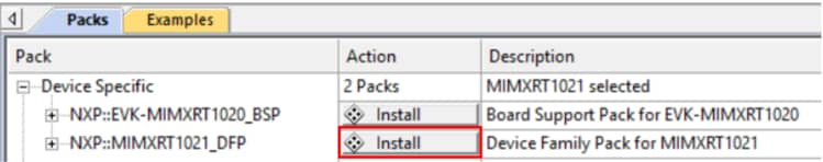
1. Install CMSIS device pack
After the MDK tools are installed, Cortex® Microcontroller Software Interface Standard (CMSIS) device packs must be installed to fully support the device from a debug perspective. These packs include things such as memory map information, register definitions and flash programming algorithms. Follow these steps to install the appropriate CMSIS pack.
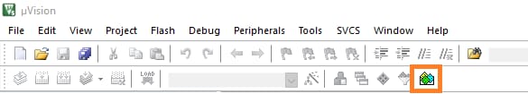
-
Open the MDK IDE, which is called µVision. In the IDE, select the "Pack Installer" icon.
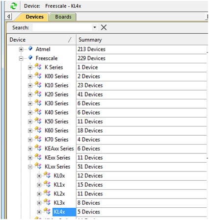
-
In the Devices tab on the left hand side of the dialog box that appears, expand the NXP category. Then expand the KLxx Series category and highlight KL4x by clicking it once.
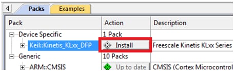
-
After the installation finishes, close the Pack Installer window and return to the µVision IDE.
Note:
This process requires an internet connection to successfully complete.
2. Build the Platform Library
These steps show how to open the demo workspace in µVision, how to build the platform library required by the demo, and how to build the demo application.
-
Demo workspace files can be found using this path:
/examples/frdmkl46z/demo_apps/ /mdk The workspace file is named
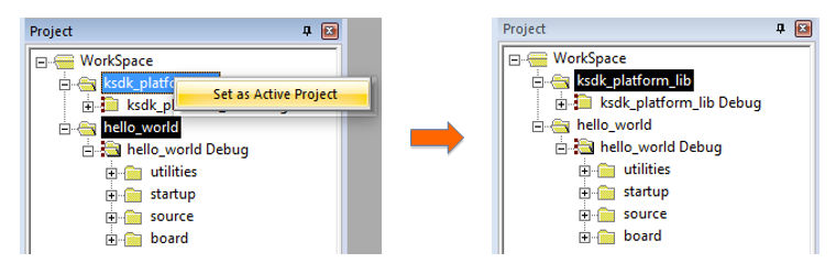
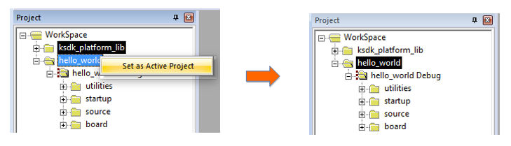
.uvmpw. For this specific example, the actual path is: /examples/frdmkl46z/demo_apps/hello_world/mdk/hello_world.uvmpw After the workspace is open, two projects show up: one for the KSDK platform library, and one for the demo. By default, the demo project is selected as the active project.
-
Make the platform library project the active project since the library is required by the demo application to build. To make the platform library project active, right click on it and select "Set as Active Project". The active project has a black box around the project name. After it is active, the platform library project is highlighted.
-
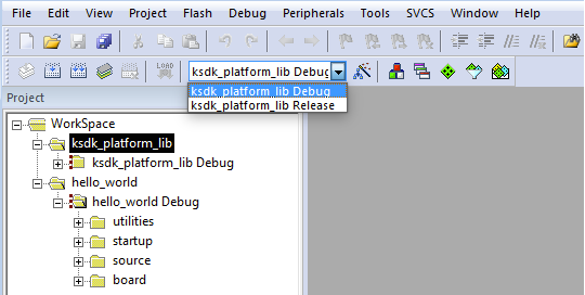
There are two project configurations (build targets) supported for each KSDK project:
- Debug — Compiler optimization is set to low, and debug information is generated for the executable. This target should be selected for development and debug.
- Release — Compiler optimization is set to high, and debug information is not generated. This target should be selected for final application deployment.
The tool allows selection of the build target based on the active project, so in order to change the configuration for the platform library it must be the active project. Choose the appropriate build target: "Debug" or "Release" from the drop-down menu.
For this example, select the "ksdk_platform_lib Debug" configuration.
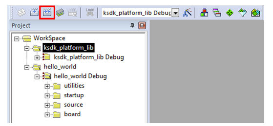
-
Rebuild the project files by left-clicking the "Rebuild" button, highlighted in red.
3. Build a Demo Application
The KSDK demo applications are built upon the software building blocks provided in the Kinetis SDK platform library, built in the previous section. If the platform library is not present, the linker displays an error indicating that it cannot find the library. If the platform library binary is not built and present, follow the steps on page 2 to build it. Otherwise, continue with the following steps to build the desired demo application.
-
If not already done, open the desired demo application workspace in:
/examples/frdmkl46z/demo_apps/ /mdk The workspace file is named
.uvmpw, so for this specific example, the actual path is: /examples/frdmkl46z/demo_apps/hello_world/iar/hello_world.uvmpw -
Make the demo the active project.
-
To build the demo project, select the "Rebuild" button, highlighted in red.

-
The build will complete without errors.
4. Run a Demo Application
The FRDM-KL46Z board comes loaded with the mbed/CMSIS-DAP debug interface from the factory. If you have changed the debug OpenSDA application on your board, visit http://www.nxp.com/opensda for information on updating or restoring your board to the factory state.
-
Connect the development platform to your PC via USB cable between the "SDAUSB" USB port on the board and the PC USB connector.
-
Open the terminal application on the PC (such as PuTTY or TeraTerm) and connect to the debug COM port you determined earlier. Configure the terminal with these settings:
- 115200 baud rate
- No parity
- 8 data bits
- 1 stop bit
-
After the application is properly built, click the "Download" button to download the application to the target.
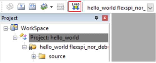
-
After clicking the "Download" button, the application downloads to the target and should be running. To debug the application, click the "Start/Stop Debug Session" button, highlighted in red.
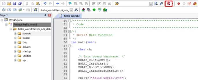
-
Run the code by clicking the "Run" button to start the application.
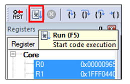
-
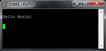
The hello_world application is now running and a banner is displayed on the terminal. If this is not the case, check your terminal settings and connections.
Running a demo using Kinetis Design Studio IDE Download PDF
1. Install Eclipse Update
Before using KDS IDE with KSDK, the KSDK Eclipse Update must be applied. Without this update, Eclipse cannot generate KSDK-compatible projects.
Windows and Mac® OS Users
The steps required for Mac OS are identical to Windows; the only difference is that the IDE looks slightly different.
-
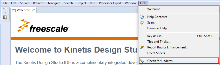
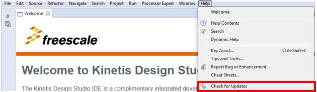
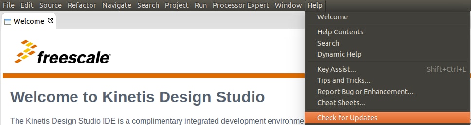
After installing KDS, check for available updates. Install the Processor Expert 3.0.1 updates from NXP only - do not install any other updates. To check for updates, select “Help” -> “Check for Updates”.
-
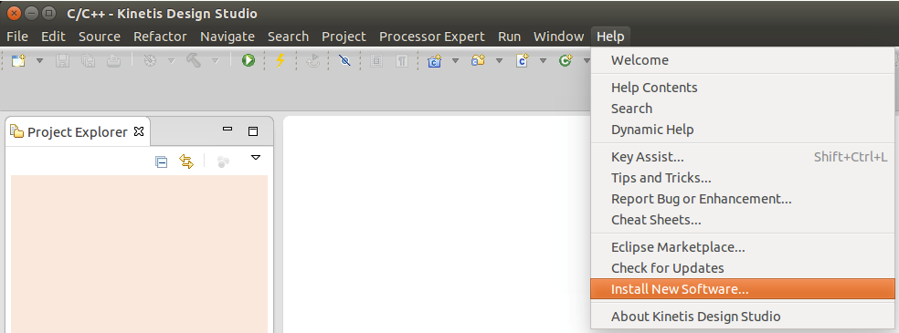
Select "Help" -> "Install New Software".
-
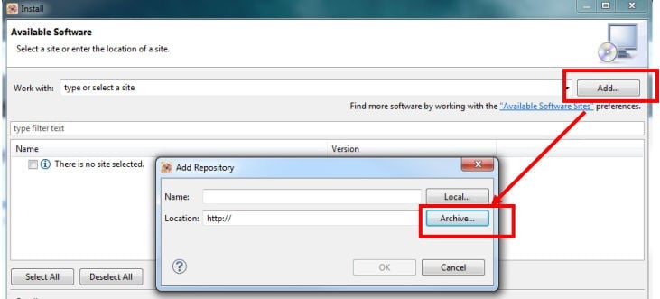
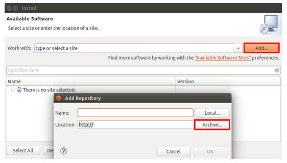
In the Install New Software dialog box, click the "Add" button in the upper right corner. Then, in the Add Repository dialog, select the "Archive" button.
-
In the Repository archive dialog box, browse the KSDK install directory
-
Enter the
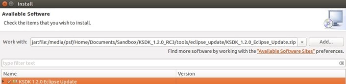
/tools/eclipse_update folder and select the KSDK__Eclipse_Update.zip file. -
Click "Open", and the "OK" button in the Add Repository dialog box.
-
The KSDK update shows up in the list of the original Install dialogs
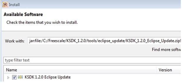
-
Check the box to the left of the KSDK Eclipse update and click the "Next" button in the lower right corner.
-
Follow the remaining instructions to finish the installation of the update.
-
After the update is applied, restart KDS for the changes to take effect.
Linux® OS Users
The following instructions were performed using Ubuntu 14.04. These steps may be slightly different for other Linux distributions.
-
Launch KDS IDE from the command line as the root user. On the command line, use this command, assuming the default KDS IDE install path:
user@ubuntu:~$ sudo /opt/NXP/KDS_x.x.x/eclipse/kinetis-design-studioThe KDS IDE version (shown above as x.x.x) should reflect the version installed on your machine, for example, 3.0.0.
-
You are prompted to enter the root password.
-
After installing KDS, check for available updates. Install the Processor Expert 3.0.1 updates from NXP only - do not install any other updates. To check for updates, select “Help” -> “Check for Updates”.
-
Select "Help" -> "Install New Software"
-
In the "Install New Software" dialog box, click the "Add" button in the upper right corner. Then, in the "Add Repository" dialog, select "Archive".
-
In the Repository archive dialog box, browse the KSDK install directory.
-
Enter the
/tools/eclipse_update folder and select the KSDK__Eclipse_Update.zip file. -
Click "Open", and "OK" in the "Add Repository" dialog box.
-
The KSDK update shows up in the list of the original Install dialogs.
-
Check the box to the left of the KSDK Eclipse update and click the "Next" button in the lower right corner.
-
Follow the remaining instructions to finish the installation of the update.
-
After the update is applied, restart the KDS IDE for the changes to take effect.
-
After KDS IDE restarts, shut down the IDE and restart by launching KDS IDE as the non-root user. To do this, follow the command in step 1, only without the "sudo" command.
2. Build the Platform Library
These steps show how to open and build the platform library project in KDS IDE. The platform library is required by the demo and does not build without it.
Note:
The steps required for Linux and Mac OS are identical to those for Windows.
-
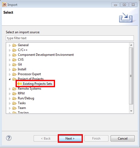
Select "File->Import" from the KDS IDE menu. In the window that appears, expand the "General" folder and select "Existing Projects into Workspace". Then, click the "Next" button.
-
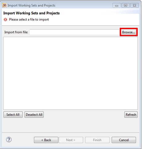
Click the "Browse" button next to the "Select root directory:" option.
-
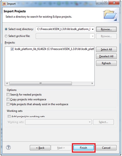
Point to the platform library project for the appropriate device, which can be found using this path:
/lib/ksdk_platform_lib/kds/KL46Z4 -
After pointing to the correct directory, your "Import Projects" window should look like the figure below. Click the "Finish" button.
-
There are two project configurations (build targets) supported for each KSDK project:
- Debug — Compiler optimization is set to low, and debug information is generated for the executable. This target should be selected for development and debug.
- Release — Compiler optimization is set to high, and debug information is not generated. This target should be selected for final application deployment.
-
Choose the appropriate build target, "Debug" or "Release", by clicking the downward facing arrow next to the hammer icon, as shown below. For this example, select the "Debug" target.
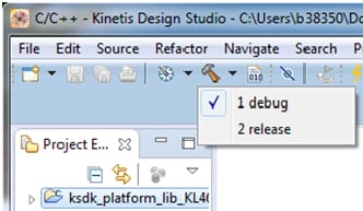
-
The library starts building after the build target is selected. To rebuild the library in the future, click the hammer icon (assuming the same build target is chosen).
4. Run a Demo Application
Note:
The steps required for Linux and Mac OS are identical to those for Windows.
The FRDM-KL46Z board comes loaded with the mbed/CMSIS-DAP debug interface from the factory. If you have changed the debug OpenSDA application on your board, visit http://www.nxp.com/opensda for information on updating or restoring your board to the factory state.
Mac users must install the J-Link OpenSDA application in order to use the KDS IDE to download and debug their board.
-
Connect the development platform to your PC via USB cable between the "SDAUSB" USB port on the board and the PC USB connector.
-
Open the terminal application on the PC (such as PuTTY or TeraTerm) and connect to the debug COM port you determined earlier. Configure the terminal with these settings:
- 115200 baud rate
- No parity
- 8 data bits
- 1 stop bit
-
For Linux OS users only, run the following commands in your terminal. These install libudev onto your system, which is required by KDS IDE to launch the debugger.
user@ubuntu:~$ sudo apt-get install libudev-dev libudev1user@ubuntu:~$ sudo ln —s /usr/lib/x86_64-linux-gnu/libudev.so /usr/lib/x86_64-linux-gnu/libudev.so.0 -
Ensure that the debugger configuration is correct for the target you're attempting to connect to. Consult Appendix B for more information about the default debugger application on the various hardware platforms supported by the KSDK.
-
To check the available debugger configurations, click the small downward arrow next to the green "Debug" button and select "Debug Configurations".
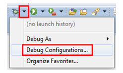
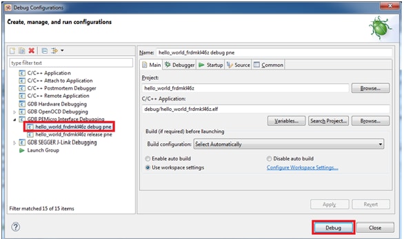
-
In the Debug Configurations dialog box, select debug configuration that corresponds to the hardware platform you're using. For Windows or Linux users, select is the CMSIS-DAP/DAPLink option under OpenOCD. For Mac users, select J-Link.
After selecting the debugger interface, click the "Debug" button to launch the debugger.
-
-
The application is downloaded to the target and automatically run to main():
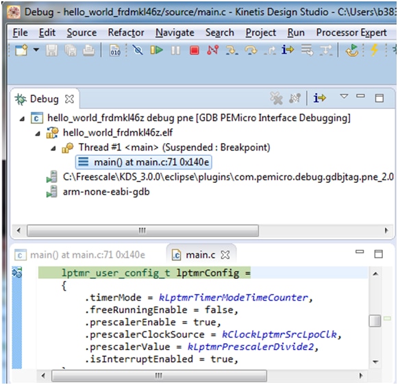
-
Start the application by clicking the "Resume" button:
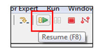
-
The hello_world application is now running and a banner is displayed on the terminal. If this is not the case, check your terminal settings and connections.

Manufacturing Tool Tutorial - Android™
- Connect a USB cable from a computer running Windows OS to the USB OTG port on the board.
- Unzip the mfgtools.tar.gz file to a selected loation. The directory is named MFGTool-Dir in this example.
- Copy the BSP image to to the path: MFGTool-Dir/Profiles/Linux/OS Firmware/files/android/sabresd
- No dedicated boot DIP switches are reserved for serial download mode on i.MX 6 Quad/QuadPlus SABRE-SD board.One way is to change the SABRE-SD SW6 (boot) to 00001100 (from 1-8 bit) to enter download mode.
- Power on the board.
- Double-click the file *.vbs according to the target device.
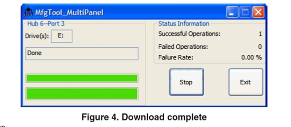
- Click "Start" to start downloading. the status bar shows the download status. The download may take one to two minutes depending on the host machine.
- After the image downloading is done, set the boot switch to boot up the board according to the table in the next step.
For details, please refer to "3.3 Downloading Board Images" in i.MX Android™ Quick Start Guide
You can connect a USB cable from the debug UART port to the computer and open a serial communication program for for console output.
Manufacturing Tool Tutorial - Linux®
- Connect a USB cable from a computer to the USB OTG port on the board.
- No dedicated boot DIP switches are reserved for serial download mode on i.MX 6 Quad/QuadPlus
SABRE-SD board.
One way is to set the boot mode to boot from SD slot SD3 but do not insert the SD card, and power on the board. After the message "HID Compliant device" is displayed, the board enters serial download mode. Then insert the SD card into SD slot SD3.See "4.5.11 Serial download mode for the Manufacturing Tool" in i.MX Linux® User Guide. - Power on the board.
- Choose the correct *.vbs file according to the target device. The manufacturing tool automatically pulls the required files based on the device. The default profile of the Manufacturing Tool assumes that your file system is packed and compressed using the bzip2 algorithm. You can also modify the profile to support other formats.
- After the image downloading is done, set the boot switch to boot up the board. See next step in Section 2 in this Getting Started Tutorial or Section "How to boot the i.MX boards" in the document.
For details, please refer to 4.2 Manufacutring Tool in i.MX Linux® User's Guide.
You can connect a USB cable from the debug UART port to the computer and open a serial communication program for for console output.
Boot Switch Setup
The boot modes of the i.MX boards are controlled by the boot configuration boot switches on the board.
The following table shows the boot switch settings (which takes priority in boot process) for booting from the SD card slot labeled SD1/J6 on the i.MX7Dual Sabre board.
Table 1. Booting from SD1/J6 on i.MX7Dual Sabre-SD
| Boot Media | SW2 [D1-D8] |
SW3 [D1-D2] |
|---|---|---|
SD card (SD1) |
00100000 | 10 |
| eMMC | 01010000 | 10 |
| NAND | 011XXXX0 | 10 |
| QuadSPI | 10000000 | 10 |
| SDP | XXXXXXXX | 01 |
Tera Term Tutorial
Tera Term Tutorial
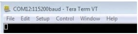
Tera Term is a very popular open source terminal emulation application. This program can be used to display information sent from your NXP development platform's virtual serial port.
- Download Tera Term from SourceForge. After the download, run the installer and then return to this webpage to continue.
- Launch Tera Term. The first time it launches, it will show you the following dialog. Select the serial option. Assuming your board is plugged in, there should be a COM port automatically populated in the list.
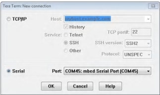
- Configure the serial port settings (using the COM port number identified earlier) to 115200 baud rate, 8 data bits, no parity and 1 stop bit. To do this, go to Setup -> Serial Port and change the settings.
- Verify that the connection is open. If connected, Tera Term will show something like below in its title bar
- You're ready to go
PuTTY Tutorial
PuTTY Tutorial
PuTTY is a popular terminal emulation application. This program can be used to display information sent from your NXP development platform's virtual serial port.
- Download PuTTY using the button below. After the download, run the installer and then return to this webpage to continue.
- PuTTY by either double-clicking on the
*.exefile you downloaded or from the Start menu, depending on the type of download you selected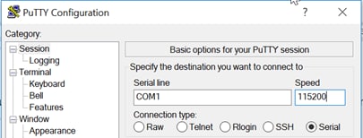
- Click Open to open the serial connection. Assuming the board is connected and you entered the correct COM port, the terminal window will open. If the configuration is not correct, PuTTY will alert you
- You're ready to go
Minicom Tutorial
Minicom Tutorial
Serial communication console setup
On the command prompt of the Linux host machine, run the following command to determine the port number:
$ ls /dev/ttyUSB*
The smaller number is for Cortex-A7 and the bigger number is for Cortex-M4.
Minicom
Use the following commands to install and run the serial communication program (minicom as an example):
- Install Minicom using Ubuntu package manager.
$ ls /dev/ttyUSB* - Launch Minicom using a console window using the port number determined earlier.
$ sudo minicom /dev/ttyUSB* -s - Configure Minicom as show in [Minicom Configuration]
- The next step is to [Connect the HDMI cable].
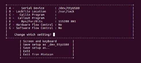
Figure 3. Minicom Configuration
On this page
- 1.1
Get Familiar with the Board
- 1.2
Insert the SD Card (SD1/J6)
- 1.3
Connect USB Debug Cable
- 1.4
Connect the HDMI cable
- 1.5
Boot Switch Setup
- 1.6
Connect Power Supply
- 1.7
Congratulations Linux® has booted
- 4.1
Overview
- 4.2
Download NXP FreeRTOS source and demos
- 4.3
Run applications using U-Boot
- 4.4
Cortex-M4 standalone sensor demo:
- 4.5
Cortex-A7/Cortex-M4 RPMsg Ping Pong demo
- 5.1
Explore the documentation
- 5.2
Board documentation
- 5.3
SoC documentation
- 5.4
Software documentation
- 5.5
Application notes
- 5.6
Key features in Linux BSP
- 5.7
Power management
- 5.8
Multimedia - Simple audio example
- 5.9
Decoder video audio
- 5.10
Security
- 5.11
CAAM and CryptoDev
- 5.12
Checking the speed performance
- 5.13
Connectivity