Application Note (1)
Brochure (1)
-
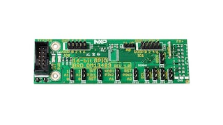
Agile I/O GPIO Brochure[AGILE-IO-GPIO-BROCHURE]
The PCAL9555A is a low-voltage 16-bit General Purpose Input/Output (GPIO) expander with interrupt and weak pull-up resistors for I²C-bus/SMBus applications. NXP® I/O expanders provide a simple solution when additional I/Os are needed while keeping interconnections to a minimum, for example, in ACPI power switches, sensors, push buttons, LEDs, fan control, etc.
In addition to providing a flexible set of GPIOs, the wide VDD range of 1.65 V to 5.5 V allows the PCAL9555A to interface with next-generation microprocessors and microcontrollers where supply levels are dropping down to conserve power.
The PCAL9555A contains the PCA9555 register set of four pairs of 8-bit Configuration, Input, Output, and Polarity Inversion registers, and additionally, the PCAL9555A has Agile I/O, which are additional features specifically designed to enhance the I/O. These additional features are programmable output drive strength, latchable inputs, programmable pull-up/pull-down resistors, maskable interrupt, interrupt status register, programmable open-drain or push-pull outputs.
The PCAL9555A is a pin-to-pin replacement to the PCA9555, however, the PCAL9555A powers up with all I/O interrupts masked. This mask default allows for a board bring-up free of spurious interrupts at power-up.
The PCAL9555A open-drain interrupt (INT) output is activated when any input state differs from its corresponding Input Port register state and is used to indicate to the system leader that an input state has changed.
INT can be connected to the interrupt input of a microcontroller. By sending an interrupt signal on this line, the remote I/O can inform the microcontroller if there is incoming data on its ports without having to communicate via the I²C-bus. Thus, the PCAL9555A can remain a simple follower device.
The device outputs have 25 mA sink capabilities for directly driving LEDs while consuming low device current.
The power-on reset sets the registers to their default values and initializes the device state machine.
The device powers on with weak pull-up resistors enabled that can replace external components.
Three hardware pins (A0, A1, A2) select the fixed I²C-bus address and allow up to eight devices to share the same I²C-bus/SMBus.
|
|
|
|
|
|
|
|---|---|---|---|---|---|
|
|
|
|
|
|
|
|
|
|
|
|
|
|
|
|
|
|
|
|
|
|
|
|
|
|
|
|
|
|
|
|
|
|
|
|
|
|
|
|
|
|
|
|
|
|
|
|
|
|
|
|
|
|
|
|
|
|
|
|
|
|
|
|
|
|
|
|
|
|
Quick reference to our documentation types
7 documents
Compact List
2 design files
Receive the full breakdown. See the product footprint and more in the eCad file.
1 hardware offering
To get further assistance directly from NXP, please see our Engineering Services.
1 engineering service

To find additional partner offerings that support this product, visit our Partner Marketplace.