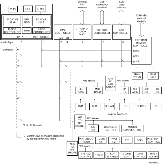
Arm926EJ-S with 128 kB SRAM, USB High-speed OTG, SD/MMC, NAND flash controller

LPC3220FET296
  • Not Recommended for New Designs
  • This page contains information on a product that is not recommended for new designs.

See product image

Product Details

Select a section:

Block Diagram

Block diagram: LPC3220FET296, LPC3230FET296, LPC3240FET296, LPC3250FET296

Features

  • ARM926EJS processor, running at CPU clock speeds up to 266 MHz
  • Vector Floating Point (VFP) coprocessor
  • 32 kB instruction cache and a 32 kB data cache
  • Up to 128 kB of Internal SRAM (IRAM)
  • Selectable boot-up from various external devices
  • Multi-layer AHB system that provides a separate bus for each AHB leader
  • External memory controller for DDR and SDR SDRAM as well as for static devices
  • Two NAND flash controllers
  • Leader Interrupt Controller (MIC) and two Follower Interrupt Controllers (SIC)
  • Eight channel General Purpose DMA (GPDMA) controller on the AHB
  • USB interface supporting either device, host (OHCI compliant), or On-The-Go
  • Four standard UARTs with fractional baud rate generation
  • Three additional high-speed UARTs intended for on-board communications
  • Two SPI controllers
  • Two SSP controllers
  • Two I2C-bus interfaces with standard open-drain pins
  • Two I2S-bus interfaces, each with separate input and output channels
  • Secure Digital (SD) memory card interface
  • General Purpose (GP) input, output, and I/O pins
  • 10 bit, 400 kHz Analog-to-Digital Converter (ADC)
  • Real-Time Clock (RTC) with separate power pin and dedicated 32 kHz oscillator
  • 32-bit general purpose high-speed timer with a 16-bit pre-scaler
  • Six enhanced timer/counters
  • 32-bit millisecond timer driven from the RTC clock
  • WatchDog timer clocked by the peripheral clock
  • Two single-output PWM blocks
  • Motor control PWM
  • Keyboard scanner function allows automatic scanning of an up to 8 x 8 key matrix
  • Up to 18 external interrupts
  • Standard Arm® test/debug interface for compatibility with existing tools
  • Emulation Trace Buffer (ETB) with 2048 x 24 bit RAM allows trace via JTAG
  • Stop mode saves power
  • On-chip crystal oscillator
  • An on-chip PLL allows CPU operation up to the maximum CPU rate
  • Boundary scan for simplified board testing

Target Applications

  • Consumer
  • Medical
  • Industrial
  • Network control

Part numbers include: LPC3220FET296.

Documentation

Quick reference to our documentation types.

1-5 of 15 documents

Show All

Design Resources

Select a section:

Design Files

4 design files

Support

What do you need help with?