Getting Started with the KITVR5510XA0EVM Evaluation Board
Contents of this document
-
Get Started
-
Get to Know the Hardware
-
Install the Software
-
Configure the Hardware
Sign in to save your progress. Don't have an account? Create one.
Purchase your KITVR5510xA0EVM | Evaluation Board for VR5510
1. Get Started
The NXP analog product development boards provide an easy-to-use platform for evaluating NXP products. The boards support a range of analog, mixed-signal and power solutions. They incorporate monolithic integrated circuits and system-in-package devices that use proven high-volume technology. NXP products offer longer battery life, a smaller form factor, reduced component counts, lower cost, and improved performance in powering state-of-the-art systems.
This page will guide you through the process of setting up and using the KITVR5510xA0EVM evaluation board.
1.1 Kit Contents/Packing List
The KITVR5510xA0EVM contents include:
- Assembled and tested KITVR5510xA0EVM connected to FRDM-K82F in an antistatic bag
- 2.6 ft USB-STD A to USB-B-micro cable
- Quick Start Guide
1.2 Additional Hardware
In addition to the kit contents, the following hardware is necessary or beneficial when working with this kit.
- Power supply with a range of 5.0 V to 24.0 V and current limit set initially to 100 mA
- Two power supply cables with banana connectors at one end
1.3 Windows PC Workstation
This evaluation board requires a Windows PC workstation. Meeting these minimum specifications should produce great results when working with this evaluation board.
- USB-enabled computer with Windows 7 or Windows 10
1.4 Software
Installing software is necessary to work with this evaluation board. All listed software is available on the evaluation board's information page.
NXP_GUI_ PR_4.1.0: software interface GUI tool to generate debug scripts.
2. Get to Know the Hardware
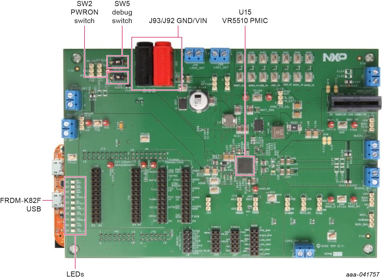
2.1 Board Features
- VR5510 debug mode support
- Supports high current testing
-
Connectors for measuring:
- Loop stability
- Load transients (BUCK12 or VPRE)
- AMUX/JTAG
- Signal and power
- Efficiency
- Load terminals for VPRE, BUCKs, BOOST, LDOs, and HVLDO regulator output
-
Jumper selection for:
- I/O control (RSTB, PGOOD, STANDBY, PWRON2, PSYNC, VDDIO)
- Debug mode entry/exit
- Switching regulators (BUCKx, VPRE) feedback
- Multiple test points
2.2 Board Description
The KITVR5510xA0EVM is a development platform built around the VR5510 PMIC as the Device Under Test (DUT). The board allows designers to evaluate various functions of the DUT. Connectors on the board provide the capability of measuring power-related functions such as power, efficiency, loop stability, load transients, etc. Jumpers on the board enable the selection of various capabilities, such as I/O control and switching regulator feedback. The EVM also allows the VR5510 to be set into Debug Mode to facilitate the debugging of faults generated by the device.
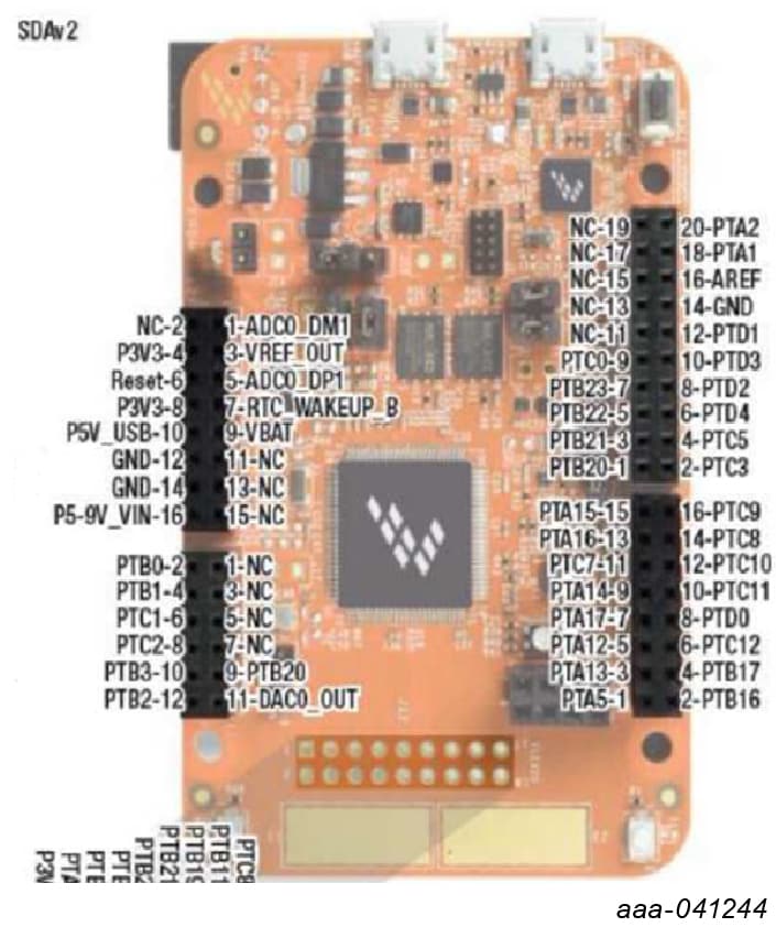
The KITVR5510xA0EVM includes NXPs FRDM-K82F development platform board. The FRDM-K82F attaches to the bottom of the board and serves as the communication interface between the KITVR5510xA0EVM and GUI software on the PC.
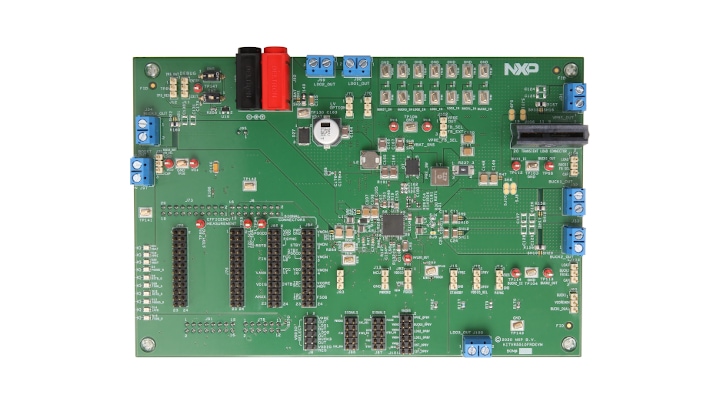
2.3 Board Components
Overview of the KITVR5510xA0EVM evaluation board.
3. Install the Software
Unzip the NXP_GUI_PR_4.1.0 into any desired location. Find the NXP_GUI-4.1.0- Setup from the GUI folder inside the package and run it to install the GUI in any desired location.
3.1 Freedom board BOOTLOADER refresh in a Windows 7 system
A pair of RDDRONE-T1 boards are used to connect two standard PCs with RJ45 connectors together over a 2-wire T1 network. The adaptors communicate with each other via T1 and the power is supplied by the PCs over USB cables.
- Ensure that the boot loader in the GUI package is the latest specified in the link below. If not, download the latest boot loader for the specific MCU (K82F) available at DAPLink bootloader update blog
-
Press the RST push button on the Freedom board and connect the USB
cable to the SDA port (J5) on the Freedom board. A new
“BOOTLOADER” device appears on the left pane of the File Explorer
- Drag and drop the downloaded file “0244_k20dx_bootloader_update_0x8000.bin” into the BOOTLOADER drive
- Disconnect and reconnect the USB cable into the SDA port (this time without pressing the RST push button)
- Drag and drop the file “k20dx_frdmk82f_if_crc_legacy_0x8000.bin” from the package (MCU/K82F_FW folder) into the BOOTLOADER drive.
- Locate the file “nxp-gui-fw-frdmk82f-usb_hid-vr5510_b0_v0.7.3.bin” from the package (MCU/K82F_FW folder) and drag and drop the file into the FRDM_K82FD device
- The Freedom board firmware is successfully loaded. Disconnect and reconnect the USB cable to the USB port. Open the previously installed NXPGUI. The “Start” button on the top left corner must be activated
3.2 Freedom Board BOOTLOADER Refresh in a Windows 10 System
- If only the NXPGUI firmware has to be updated, start from Step 4 in Section 3.1 "Freedom board BOOTLOADER refresh in a Windows 7 system". The PC detects FRDM_K82FD. Proceed to Step 6 to load the latest firmware file received from NXP and follow up with Step 7
- Download the latest bootloader from this location below for the specific MCU (K82F): DAPLink bootloader update blog
-
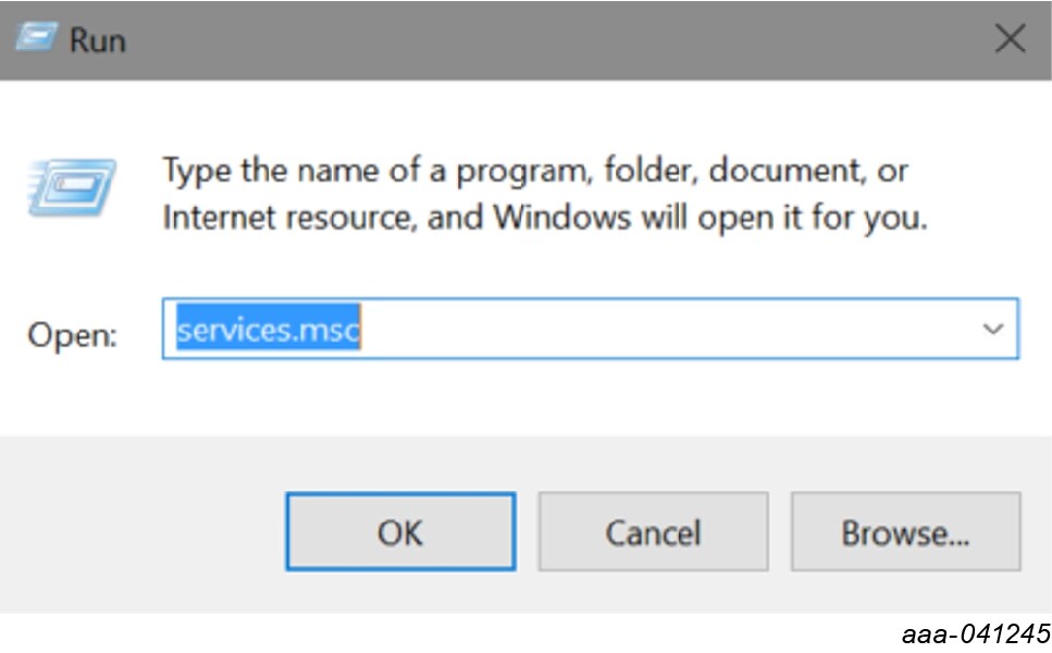
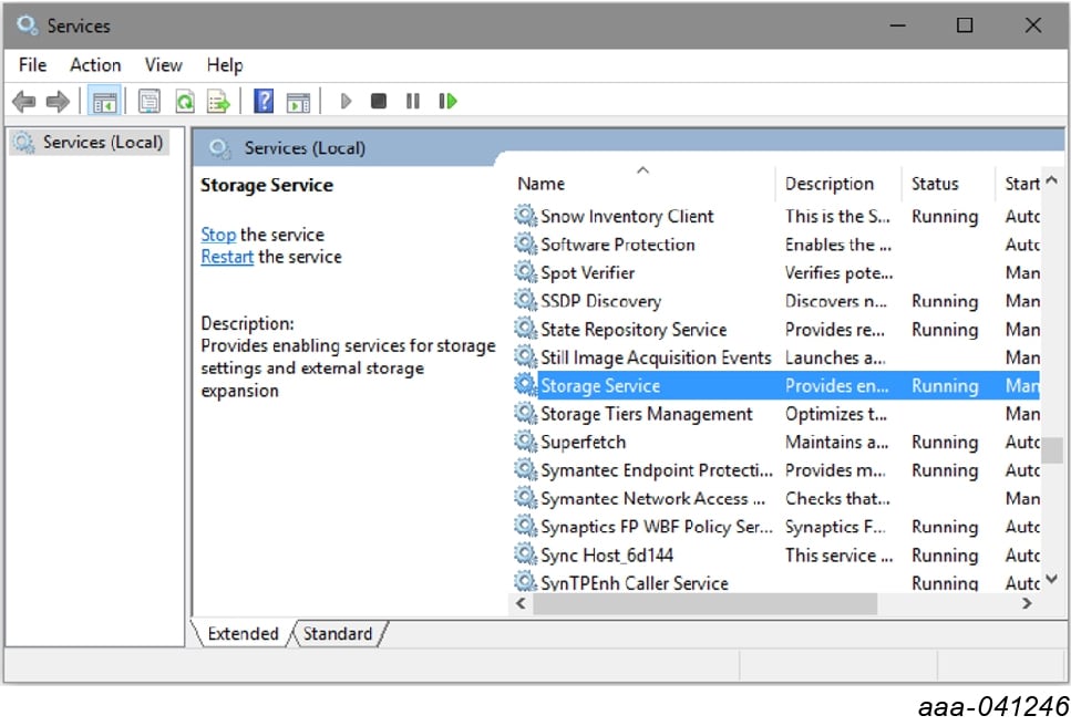
Disable the storage services: Run services.msc, then double click
on the storage service from the list and press the stop button
- Press the RST push button on the Freedom board and connect the USB cable to the SDA port (J5) on the Freedom board. A new “BOOTLOADER” device appears on the left pane of the File explorer
- Drag and drop the downloaded boot loader file into the BOOTLOADER drive
- Disconnect and reconnect the USB cable to the SDA port (this time without pressing the RST push button). The drive is changed to “MAINTENANCE”
- Follow Steps 5-7 from Section 3.1 "Freedom board BOOTLOADER refresh in a Windows 7 system"
- If only firmware update is required, then repeat Step 1 above
- Re-enable the services by following Step 2, but now pressing the Start button
4. Configure the Hardware
4.1 Configure the Hardware
To configure the hardware and workstation, complete the following procedure:
-
With the USB cable connected to the PC and the USB port in the
FRDM-K82F, apply power to the evaluation board:
-
Provide 12 V externally on
J92andJ93(VIN/VBAT, GND) - Ensure that the jumpers and switches are configured. Configuring the jumpers and switches is only required if the board comes without a preconfigured jumper set
-
Provide 12 V externally on
- To ensure that the board is properly recognized, press the Reset button on the Freedom board
- Run the installed NXPGUI application from the start menu or the installation folder
- A configuration window appears. Select the kit type and the device silicon version and click OK.
-
To enable the connection to the device, click the Start button.
When the device is connected properly, the Start button is active
and the system is ready for normal or debug operation
- If the NXPGUI does not recognize the FRDM-K82F board or if the Start button does not activate the device, it is possible that the interface is broken. In this case, reprogramming of the FRDM-K82F board can be attempted by following steps in Section 3.1 "Freedom board BOOTLOADER refresh in a Windows 7 system"
Design Resources
Board Documents
Software
Support
Forums
Connect with other engineers and get expert advice on designing with the RDDRONE-T1ADAPT Evaluation Board on one of our community sites.