Technical content and expertise to help jump start your design and get you to production faster.
Start your designDownload our latest development and embedded software solutions.
Expedite time-to-market with our extensive lineup of development kits.
Jump-start your design with proven hardware and software solutions.
Get the latest specifications in our technical documentation library.
Further your technical expertise with online and in-person instruction.
Get comprehensive paid support to fast-track your product development.
Design ideas, demo videos, quality answers. Connect with NXP professionals and other knowledgeable designers ready to help.
Software, documentation, evaluation tools. The resources to build comprehensive solutions and accelerate your time to market.
Access our design resource libraryWe're always looking for passionate and talented people to work with us.
Join our teamThe ColdFire® DSP Library contains digital signal processing algorithms optimized for the ColdFire architecture. These algorithms are implemented directly in assembly for computational efficiency and then encapsulated into a simple C interface. In addition, a large number of predefined and pretested filter configurations are provided in order to reduce the need for a user to design digital filters.
The library is designed to enable embedded sensor applications with basic signal processing functionality, but without the need for a DSP co-processor. By taking advantage of an on-chip multiply-accumulate unit (MAC), a ColdFire microcontroller can efficiently execute DSP algorithms.
Parameter | Options | Implications |
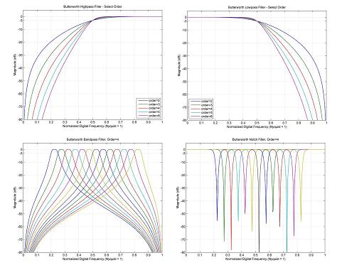
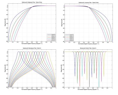
Shape | lowpass, highpass, bandpass, notch | Shape of frequency response, i.e., are high frequencies passed through or attenuated |
Order | 2,3,4,5,6 | Rolloff steepness. Higher orders roll off faster but require more MCU bandwidth |
Cutoff | varies by order, most cover 0.20-0.80 range in 0.05 increments | Digital cutoff frequency (-3dB). Related to analog frequency by sample rate, |
The following table identifies all filter configurations included in the library. Each combination of filter shape, order and cutoff constitutes a single filter configuration. Each configuration comes with four parameters – filter coefficients array, numerator scale factor, denominator scale factor, and filter order. The configurations below are all characterized as Butterworth IIR filters.
Shape | Order | Minimum Cutoff | Cutoff Increment | Maximum Cutoff |
Lowpass | 2 | 0.20 | 0.05 | 0.85 |
3 | 0.20 | 0.05 | 0.85 | |
4 | 0.25 | 0.05 | 0.80 | |
5 | 0.25 | 0.05 | 0.80 | |
6 | 0.25 | 0.05 | 0.75 | |
Highpass | 2 | 0.20 | 0.05 | 0.80 |
3 | 0.20 | 0.05 | 0.80 | |
4 | 0.25 | 0.05 | 0.75 | |
5 | 0.25 | 0.05 | 0.75 | |
6 | 0.25 | 0.05 | 0.75 | |
Bandpass | 4 | 0.20 | 0.05 | 0.80 |
Notch | 4 | 0.20 | 0.05 | 0.80 |