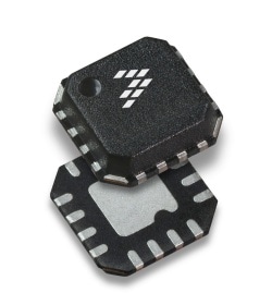
Design Files
Receive the full breakdown. See the product footprint and more in the eCad file.

| Characteristic | Symbol | 250 MHz |
900 MHz |
4000 MHz |
Unit |
| Insertion Loss | IL | –0.6 | –0.7 | –1.3 | dB |
| Attenuation Accuracy (Worst Case State) | — | +0.1, –0.1 | +0.1, 0 | +0.1, –0.1 | dB |
| Third Order Intercept Input Point(2) | IIP3 | 47 | 54 | 52 | dBm |
| Power Input @ 1 dB Compression | P1dB | 30 | 35(3) | 35(3) | dBm |
|
|
|
|
|
|
|
|---|---|---|---|---|---|
|
|
|
|
|
|
|
|
|
|
|
|
|
|
|
|
|
|
|
|
|
|
|
|
|
|
|
|
|
|
|
|
|
|
|
|
|
|
|
|
|
|
|
|
|
|
|
|
|
|
|
|
|
|
|
|
|
|
|
|
|
|
|
|
|
|
|
|
|
|
Quick reference to our documentation types.
3 documents
Please wait while your secure files are loading.
Receive the full breakdown. See the product footprint and more in the eCad file.

Receive the full breakdown. See the product footprint and more in the eCad file.